
Critical 220 MVA GSU transformer maintenance for leading Saudi refinery
How Petrozone executed multi-chamber degassing on 60,000 litres of dielectric oil, serviced oil-filled 230 kV cable boxes and OLTC compartments, and passed a ten-point electrical diagnostic battery on schedule during a major refinery turnaround.

Why a Generator Step-Up Transformer leaves zero margin for turnaround delays
In a distribution substation, losing one feeder transformer usually shifts load onto a redundant tie breaker through automatic transfer logic. A Generator Step-Up Transformer (GSUT) inside a captive Saudi refinery power island enjoys no such luxury. Sitting directly between the 18 kV synchronous gas/steam turbine generator terminals and the 230 kV high-voltage utility grid, a 165/220 MVA (ONAN/ONAF, 18/230 kV, 60 Hz, vector group YNd1) GSUT carries continuous near-nameplate megawatts day and night, exposed to steep generator step-loading thermal cycles, harmonic currents and grid switching surges.
If a GSU transformer misses its turnaround return-to-service milestone by even twenty-four hours, an entire cogeneration train stays offline and refinery steam-and-power balance stalls. Conversely, rushing oil handling or skipping proper high-voltage cable-chamber isolation on a 230 kV class asset invites trapped gas bubbles inside high-stress cellulose barriers—a mistake that can destroy a unit within minutes of re-energisation.
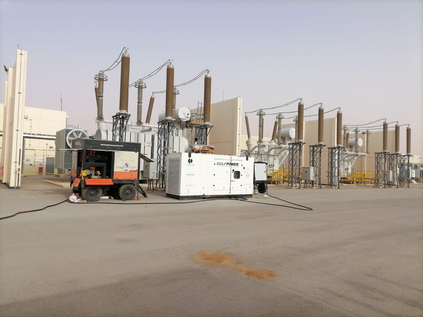
When a major Saudi refinery scheduled a critical-path turnaround on its 220 MVA GSU unit, Petrozone’s transformer maintenance and high-voltage diagnostics teams were entrusted with the complete mechanical, oil-processing and electrical scope under strict refinery HSE gas-testing, hot-work/cold-work permitting and secondary spill-containment rules.
Unlike standard outdoor bushings where overhead conductors unbolt in open air, this 220 MVA unit terminated its high-voltage phases inside oil-filled 230 kV HV cable boxes alongside a segregated On-Load Tap Changer (OLTC) diverter compartment and a 60,000-litre main tank—meaning three completely separate dielectric oil volumes had to be isolated, drained or circulated, tested and restored without cross-contaminating a single drop.
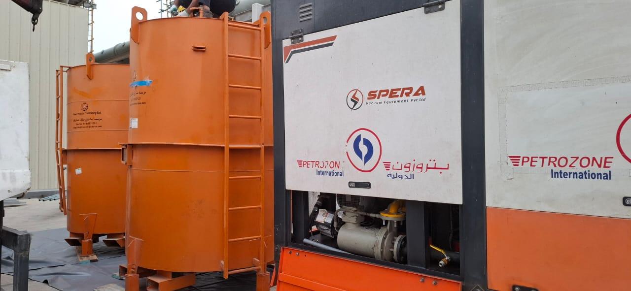
Segregating 60,000 litres of main-tank oil from carbonised OLTC and 230 kV cable-chamber fluid
Cross-contamination is a classic pitfall when inexperienced contractors service multi-compartment transformers. Over years of load-tap switching, an On-Load Tap Changer diverter compartment naturally accumulates free carbon particles and switching arc gases (acetylene and ethylene). If a crew uses the same un-flushed transfer hose or filter cartridge on the main 60,000-litre winding tank after draining the OLTC, trace carbon particles and acetylene carry over into the main tank—corrupting future Dissolved Gas Analysis (DGA) trends and lowering dielectric impulse strength.
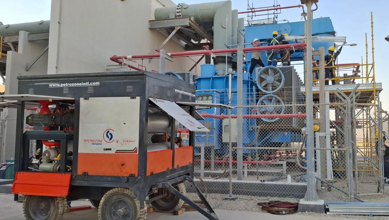
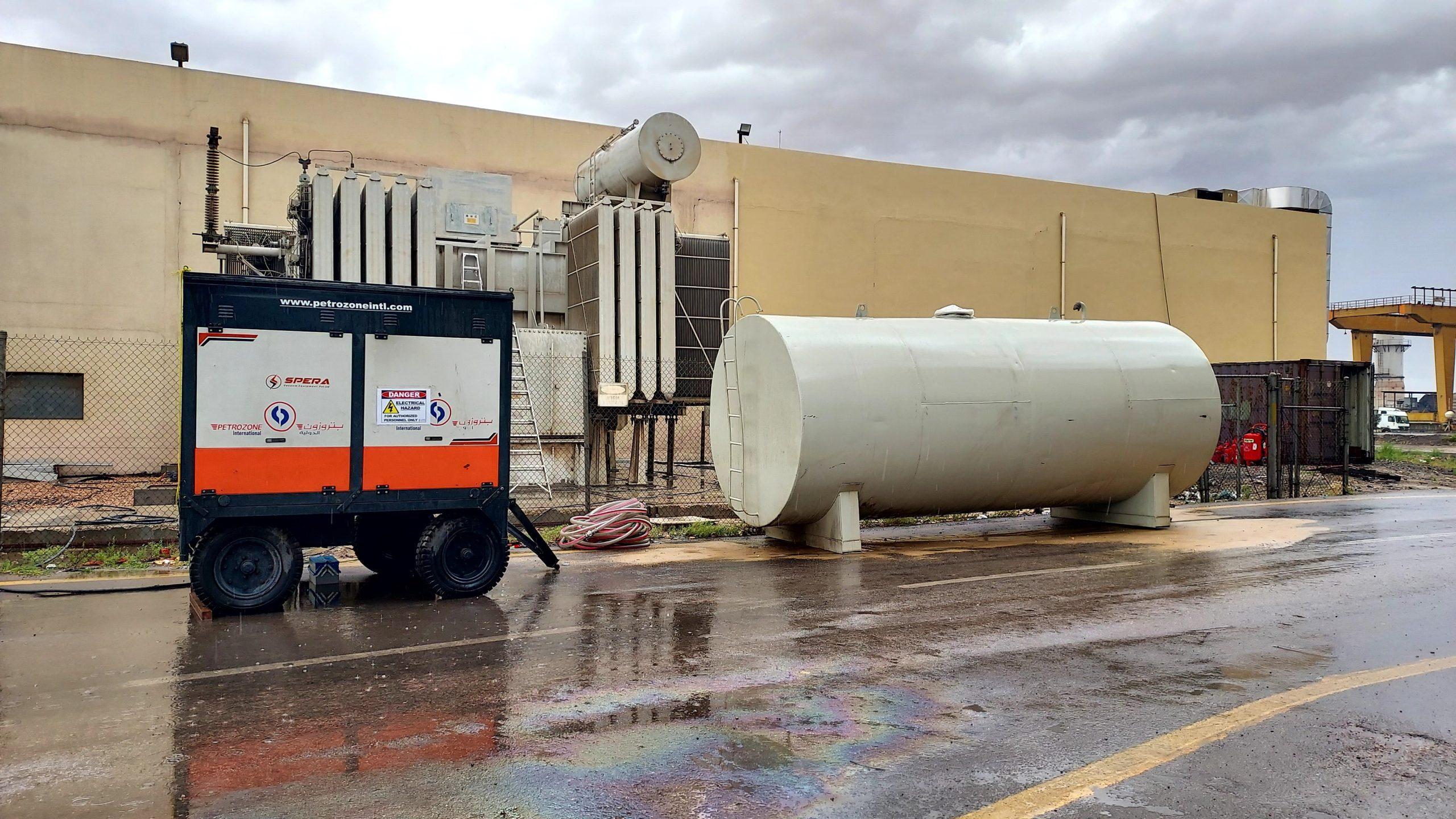
Before opening a single drain flange, our heavy logistics and site crew positioned dedicated closed-loop storage tanks, bunded drip trays, calibrated flow manifolds and two-stage high-vacuum dehydration/degassing plants at the substation apron. Every hose run was colour-tagged and dedicated by compartment:
- 60,000-Litre Main Winding Tank: Connected in a continuous closed-loop hot-oil vacuum circulation path—drawing from the bottom manifold, heating gently under controlled watt-density heaters (preventing local oil scorching above 65 °C that would generate stray hydrocarbon gases), passing through 1-micron particulate beta-rated elements and < 1 mbar vacuum degassing towers, and returning via top manifold until moisture, dissolved gas content and Breakdown Voltage (BDV) hit peak benchmarks.
- 230 kV Oil-Filled HV Cable Chambers: Safely drained into clean, sealed holding vessels under dry breather protection so bolted access covers could be opened and internal heavy copper disconnecting links removed—a mandatory step to electrically isolate the transformer HV windings from the capacitance of the underground 230 kV XLPE export cables before running Tan Delta and Turns Ratio diagnostics.
- On-Load Tap Changer (OLTC) Compartment: Drained separately for internal contact wear inspection, carbon-sludge flushing, barrier board inspection and refill/filtration with clean specification mineral insulating oil—preventing any carbon carryover into core-and-coil oil.
Throughout multi-pass circulation on the 60,000-litre main volume, field technicians drew inline glass-bottle and gas-tight syringe checks after every complete tank turnover—verifying IEC 60156 dielectric Breakdown Voltage climbing cleanly above 70–75 kV across a 2.5 mm electrode gap, moisture dropping well below 5–8 ppm, and total dissolved gas content stripped down so cellulose paper moisture could equilibrate safely.
Reading Dissolved Gas Analysis on a heavily loaded 220 MVA generator transformer
Interpreting Dissolved Gas Analysis (DGA) on a refinery Generator Step-Up Transformer demands context that generic automated software reports often miss. Because a GSUT operates near eighty-five to ninety-five percent continuous load factor behind a base-load cogeneration turbine—and handles generator harmonic currents plus stray leakage flux in heavy core clamps and tank shields—its baseline thermal gas signature looks very different from a lightly loaded distribution substation transformer.
Before connecting our high-vacuum degassing skids, Petrozone’s diagnostics engineers reviewed historical IEC 60599 / IEEE C57.104 gas trends alongside fresh pre-outage syringes drawn from all three oil zones. On a healthy mineral-oil GSU unit, mild stray-flux heating in steel clamping plates can produce modest methane (CH4) and ethane (C2H6) studied via Duval Triangle 4, whereas rising ethylene (C2H4) above 50–100 ppm warns of higher-temperature local hot spots (> 300–700 °C) on loose core-ground straps, selector contacts or brazed winding leads.
Acetylene (C2H2) is the non-negotiable red flag in a 230 kV main tank: even 1 to 2 ppm of fresh acetylene warrants immediate investigation for high-energy arcing—or for a leaking internal barrier gasket allowing switching oil from the On-Load Tap Changer diverter housing to seep across into the main winding oil! Equally informative is the ratio of carbon dioxide to carbon monoxide (CO2 / CO) paired with 2-furfuraldehyde (2-FAL) furan analysis, which reveals whether thermally upgraded Kraft paper insulation inside the hottest upper winding discs is aging cleanly or suffering accelerated depolymerisation from moisture and oxygen.
Stripping dissolved gases down near zero during our 60,000-litre hot-oil vacuum circulation gave the refinery a clean chemical slate—making post-energisation 24-hour, 7-day and 30-day DGA comparison syringes hyper-sensitive to even the smallest thermal or dielectric anomaly upon startup.
Checking ONAF cooling fans, conservator air-cells, Buchholz relays and gasket integrity
While oil treatment progressed and HV cable-box links stood open under full LOTO control, mechanical technicians executed a top-to-bottom physical and protection-device audit across the 220 MVA tank. Large refinery GSUTs vibrate harder than distribution units because magnetostriction at high flux density combines with multi-fan ONAF forced-air cooling racks.
Applying the same flange-and-elastomer inspection rigour detailed in our transformer oil leak engineering guide and proven on 150 MVA petrochemical transformer overhauls, the crew inspected turret joints, radiator isolation butterfly valves, conservator nitrile air-cell (bag) integrity, silica-gel dehydrating breathers, dial-type Oil and Winding Temperature Indicators (OTI / WTI), Pressure Relief Devices (PRDs) and dual-float Buchholz gas/surge relays.
Particular attention went to the ONAF forced-air cooling control cabinet and fan banks bridging the jump from 165 MVA (ONAN) to full 220 MVA (ONAF) summer rating. Every cooling-fan motor underwent 1,000 V DC insulation resistance testing, three-phase running-current balance checks, bearing vibration/noise listening and—simple as it sounds—physical airflow-direction verification with ribbon telltales! On almost one in five older industrial plants, at least one replaced or rewound fan motor is wired with two phases swapped, blowing hot air downward against natural oil thermosiphon convection and stealing megavolt-amperes of summer cooling margin.
Meanwhile, oil-level pockets inside the Winding Temperature Indicator (WTI) thermal imaging wells were topped up with clean transformer oil and checked against calibrated RTD/heater CT secondary currents so fan Stage 1, fan Stage 2, high-temperature alarm and master trip setpoints tracked true winding hot-spot behaviour. Every protection contact on the Buchholz relay, OLTC oil-surge relay, PRD micro-switch and WTI/OTI stages wasn’t merely buzzed locally with a multimeter—it was functionally actuated right back through the marshalling kiosk to the generator/transformer 86G/86T lockout protection panel so operations witnessed confirmed alarm and trip annunciation on the refinery DCS.
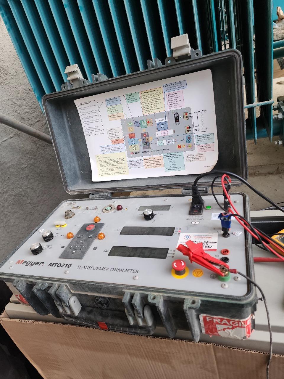
Inside the ten-point electrical test battery on an 18/230 kV YNd1 winding
With both the 18 kV iso-phase generator bus links and the 230 kV internal cable-chamber links disconnected and isolated, Petrozone’s senior testing and commissioning engineers ran a complete ten-point electrical diagnostic sweep—comparing every phase and tap reading against original factory Acceptance Test (FAT) certificates and previous turnaround records.
Testing a 220 MVA, 18/230 kV YNd1 transformer accurately requires patience with inductive time constants and electrostatic interference inside a live 230 kV switchyard. When injecting DC current to measure Winding Resistance (WR) on a low-voltage 18 kV delta winding rated over seven thousand amperes, core saturation takes substantial time; cutting the reading early before core flux stabilises produces fake phase-to-phase percentage errors that trigger false alarms about loose tap leads. Using high-current dual-channel transformer ohmmeters with automatic core demagnetisation afterward ensured every tap position stabilized within < 0.5% of sister phases—and demagnetising the core at the end prevented severe inrush currents from tripping differential relays upon re-energisation.
Equal discipline governed 230 kV condenser bushing C1 and C2 Tan Delta / Capacitance testing and 3-phase Magnetic Balance / Excitation checks. Oil-impregnated paper (OIP) and resin-impregnated paper (RIP) 230 kV bushings grade high-voltage stress across concentric aluminium foil layers. Even a single punctured foil layer raises C1 capacitance by two to five percent long before an external crack appears—warning of imminent bushing explosion if ignored. And once C2 tap testing finishes, our QA hold sheet requires two engineers to independently photograph and sign off that the bushing test-tap grounding spring cap is screwed tight, because leaving a bushing test tap floating open lets capacitive voltage destroy the bushing within minutes of energisation.
Alongside winding and bushing dielectric loss, Short-Circuit Impedance (%Z) / Leakage Reactance and low-voltage Magnetic Balance checks verified that decades of generator synchronising transients and external grid faults had caused zero radial buckling or axial clamping shift inside the 220 MVA winding cylinders.
1. Capacitance & Tan Delta (Power Factor)
10 kV GST/UST dielectric loss measurements (CHL, CH, CL) plus C1/C2 condenser bushing tests—verifying moisture-free cellulose (< 0.35% Tan δ temperature-corrected to 20 °C) and zero shorted bushing foil layers.
2. Insulation Resistance & Polarization Index
5 kV / 10 kV DC Megger tests (HV-E, LV-E, HV-LV) logged at 15 s, 1 min and 10 min—confirming clean gigaohm values and Polarization Index (PI > 2.0) after oil processing.
3. TTR & Vector Group Verification (YNd1)
Three-phase Transformer Turns Ratio and phase-displacement angle checks across every tap step—proving within ±0.1–0.2% of calculated nameplate ratio with zero shorted turns.
4. DC Winding Resistance & Core Demagnetisation
Four-wire Kelvin micro-ohm / milli-ohm sweep across all HV tap positions and LV delta phases—verifying OLTC selector contact health followed by automated core demagnetisation.
| Diagnostic Test / Process Stage | Applicable Standard | Target Engineering Acceptance Criterion | Turnaround Result |
|---|---|---|---|
| Main Tank & HV Chamber Oil BDV | IEC 60156 / IEC 60422 | > 70 kV (2.5 mm gap after vacuum treatment) | Passed (> 75 kV verified) |
| Moisture in Oil & Laboratory DGA | ASTM D1533 / IEC 60599 | < 5–8 ppm water; zero active fault-gas growth | Passed (Clean lab clearance) |
| Winding & Bushing Tan Delta (20 °C) | IEEE C57.152 / IEC 60076 | < 0.5% max (< 0.35% achieved), stable C1 capacitance | Passed across HV & LV |
| Turns Ratio (TTR) & Magnetic Balance | IEC 60076-1 | Ratio error < ±0.5% across all taps; balanced flux distribution | Passed on all tap steps |
| 10 kV Excitation Current Sweep | IEEE C57.152 | Expected High-Low-High 3-phase magnetising pattern | Passed — core laminations healthy |
| HV Cable Chamber Vacuum Refill | OEM / Aramco SAES-P | Deep vacuum hold + degassed oil refill + rest period | Zero leaks, zero trapped gas |
Vacuum-refilling the 230 kV cable chambers, mandatory settling time and clean synchronisation
Once every diagnostic curve passed review by both Petrozone's lead electrical engineer and the refinery's reliability authority, the most delicate phase began: re-bolting and torque-marking the internal 230 kV HV cable links with calibrated wrenches, verifying micro-ohm contact resistance across every remade copper palm joint so no internal hot spot could form inside the sealed oil box, fitting new OEM chamber gaskets, and restoring the oil-filled 230 kV cable boxes.
At 230 kV, electric field stress around cable-termination stress cones and condenser bushing lower shields tolerates zero trapped air bubbles. Rather than gravity-filling the chambers, our crew evacuated the sealed HV cable compartments under deep vacuum, vacuum-transferred freshly filtered, degassed insulating oil through dedicated clean hoses, bled every upper vent plug until bubble-free solid oil streams confirmed full submergence, and drew post-fill syringes from all three compartments—main tank, OLTC and 230 kV cable boxes—for independent laboratory Dissolved Gas Analysis (DGA) verification.
Equally vital, we enforced the mandatory 24-hour high-voltage oil dielectric settling window prior to 230 kV back-energisation (per IEC 60076 / IEEE C57.93 guidance for ≥ 230 kV class units), giving any microscopic residual gas equilibrium time to absorb cleanly out of high-stress pressboard wedges while downstream medium-voltage switchgear panels and online condition monitoring loops completed final pre-startup checks.
At startup, the 220 MVA GSU transformer was soaked at rated voltage for the soak hold before ramping generator megawatt load smoothly on schedule—exhibiting rock-steady 87T differential currents, clean 24-hour post-energisation DGA verification, normal top-oil and winding thermal profiles, zero oil seepage and a complete QA/QC test binder handed over for the refinery's permanent asset dossier, backed across vendor supply checks and mechanical rigging by our integrated quality inspection and electrical power systems divisions. Planning an upcoming GSU, grid-intertie or industrial furnace transformer turnaround in Saudi Arabia? Explore more engineering reports on our sample blogs hub, review our 72-hour substation turnaround case study, or request a turnaround execution plan from our Al-Khobar engineering office.
More from our engineers & field teams
Repairing oil leaks on 150 MVA power transformers at a Saudi petrochemical plant
Full-scope leak remediation across radiator flanges, pressure relief devices and valve connections to restore reliability on critical high-voltage units.
Read article →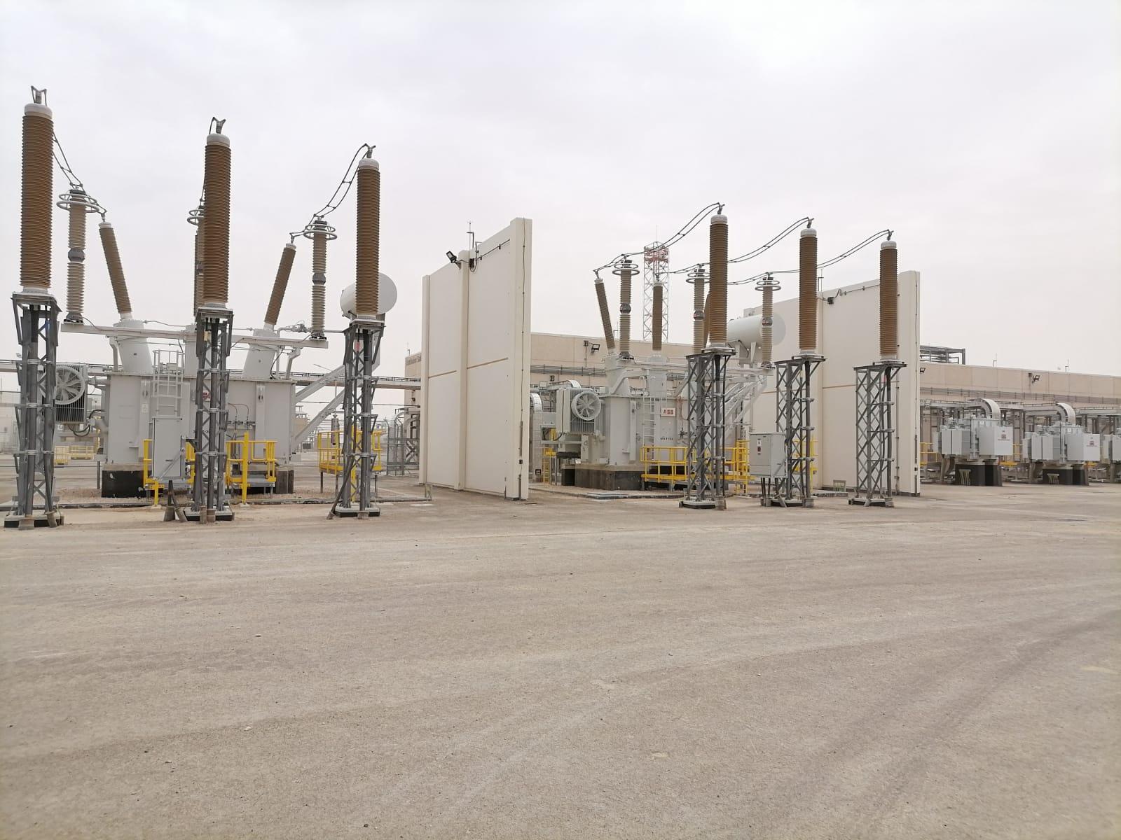
Transformer oil leaks: every leak type, why it happens and how to stop it
Common leak points on power transformers, why gaskets and welds fail in Gulf heat, and how to fix them permanently without repeat outages.
Read article →
UHF partial discharge monitoring: 24/7 switchgear protection in Saudi Arabia
How continuous UHF sensing detects early insulation defects inside medium- and high-voltage switchgear before failure occurs.
Read article →Planning a project? Talk to the right division.
Send us the scope, location and timeline. We will reply with the right team and a quote.