
Transformer oil leaks: every leak type, why it happens and how to stop it
A practical field manual on locating, diagnosing and permanently sealing insulating oil leaks on high-voltage power transformers in Saudi Arabian substations, refineries and petrochemical plants.
Why a slow oil weep on a power transformer never stays small
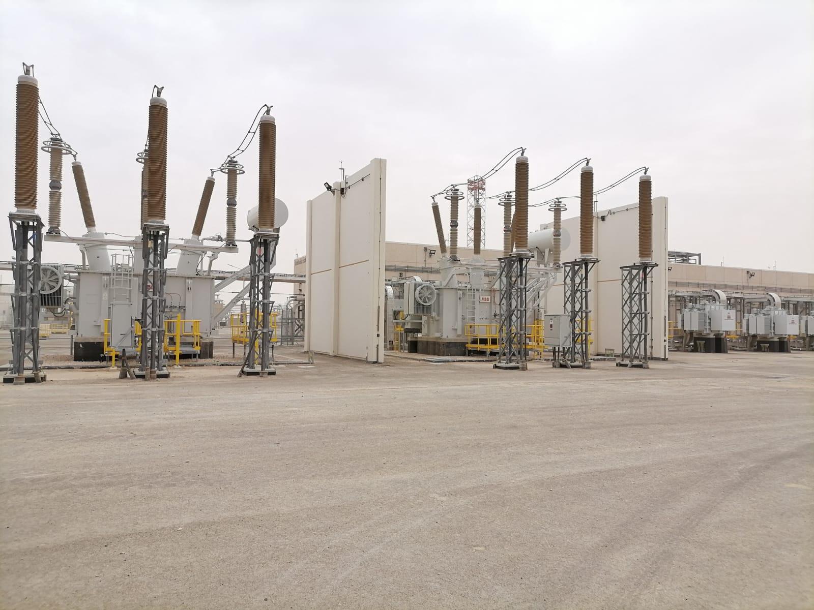
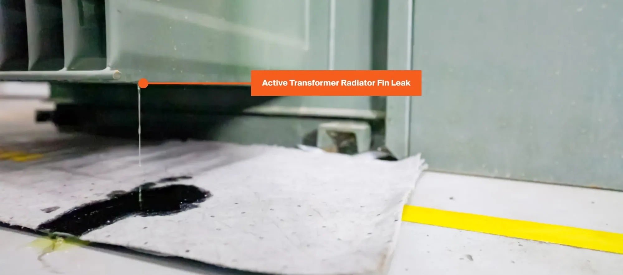
Walk around any twenty-year-old outdoor substation in Jubail, Yanbu or Dammam in August and look closely at the concrete plinths under the radiator banks. Almost every serious transformer outage our field crews are called to investigate started months earlier as a dark, dust-caked film around a bottom butterfly valve or a faint sheen down a low-voltage porcelain skirt. Because the unit stays online and top-oil temperature looks normal on the control room screen, maintenance planners often log it as a housekeeping item for a future shutdown.
That delay is where the real damage happens. Mineral insulating oil inside a power transformer does two jobs at the same time: it carries heat out of the core-and-coil assembly into the cooling radiators, and it impregnates the Kraft paper and pressboard insulation to sustain dielectric strength across high-voltage clearances. A gasket joint that lets hot oil weep outward during daytime peak load will pull humid ambient air inward when load drops after midnight and the oil column contracts.
Along the Arabian Gulf coast, night-time relative humidity routinely climbs past eighty percent. Once moist air enters through a tired flange seal or a cracked Buchholz cable gland, water migrates straight out of the oil and into the hygroscopic cellulose winding paper, which holds roughly ninety-eight percent of a transformer’s total moisture. Every six to eight parts per million of added paper moisture cuts the remaining mechanical life of that paper roughly in half. By the time a low-oil-level alarm finally annunciates on the local marshalling kiosk, dissolved moisture and oxygen have already accelerated furan formation and weakened the winding’s ability to survive a downstream through-fault.
During our transformer maintenance and oil purification programmes across Saudi industrial facilities, we treat active oil seepage as an insulation-integrity defect rather than a cosmetic drip. Understanding where a transformer leaks, why specific elastomers and welds give up under Kingdom operating conditions, and which repair method actually holds pressure for the next decade saves operators from forced outages that cost far more than a planned gasket overhaul.
Why gaskets and flange faces age twice as fast in Saudi Arabia
Gasket service intervals printed in European or North American OEM manuals assume mild ambient temperatures and modest daily temperature swings. An outdoor 132/13.8 kV or 230/34.5 kV transformer sitting in an unshaded yard in the Eastern Province lives in a completely different mechanical environment. Summer shade temperatures reach 48 to 50 °C, direct solar radiation drives painted tank covers past 70 °C, and heavy industrial loads keep top-oil temperatures between 75 and 85 °C for weeks at a stretch.
Then winter arrives in the desert interior, and overnight ambient temperatures drop below 10 °C during a feeder outage. That wide thermal delta forces dissimilar-metal joints—cast aluminium bushing mounting flanges bolted to carbon-steel turrets, brass drain valves threaded into steel bosses, and heavy detachable radiator headers—to expand and contract at different rates every twenty-four hours. Standard commercial nitrile (NBR) or low-binder cork-neoprene gaskets lose their plasticisers under continuous heat, shrinking in cross-section until contact stress against the steel groove drops below internal hydrostatic head pressure.
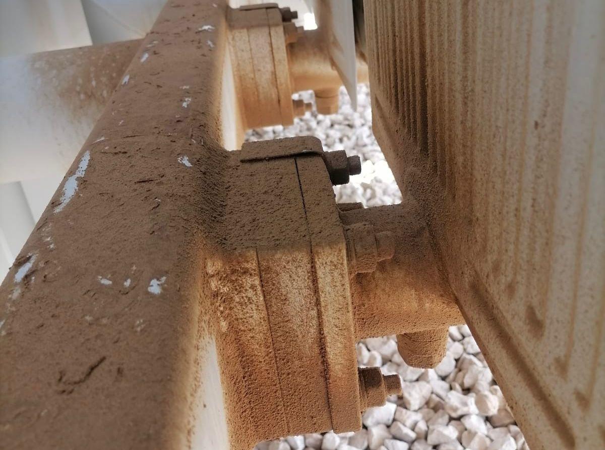
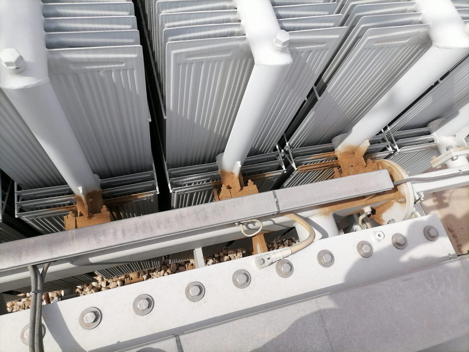
Airborne chemistry compounds the mechanical fatigue. In coastal refineries and desalination substations, windborne salt mist settles into the narrow crevice outside the gasket ring. Combine salt, morning condensation and bare carbon steel where factory paint was nicked during original erection, and crevice corrosion pits right across the sealing land. Even if you fit a brand-new gasket onto a pitted flange without dressing and re-profiling the metal seating surface first, oil will track straight underneath the new elastomer through the rust grooves within weeks.
Fine silica dust from seasonal shamal winds adds mechanical wear on upper accessories. Abrasive quartz dust packs around valve stems, tap-changer shafts and pressure-relief skirts—scoring polished sealing surfaces unless weather caps and stem boots are kept intact.
The eleven leak interfaces every substation walkdown must inspect
Locating the true origin of a transformer leak takes patience because hot mineral oil is thin, wicks sideways along weld seams, and gets blown backward across the tank cover by cooling fans. Before condemning a main tank cover gasket, our electrical power systems field engineers degrease the suspect zone with residue-free solvent, dust vertical seams lightly with developer chalk when needed, and trace upward to the highest wet point.
Across hundreds of substation inspections and 150 MVA petrochemical transformer leak repairs, ninety-five percent of oil leaks trace back to eleven recurring interfaces. Grouping them by elevation—from turret top down to plinth level—keeps nothing hidden during pre-turnaround scoping.
1. HV & LV Bushing Mounting Flanges & Top Caps
Oil running down porcelain or composite sheds starts either at the turret-to-bushing mounting flange or up at the draw-lead top terminal cap where O-rings bake directly above the hottest oil layer.
2. Radiator Isolation Butterfly Valves & Flanges
A twenty-bank transformer has forty large top-and-bottom radiator flange joints plus forty valve-stem glands—making radiator headers the number-one high-volume leak source on units older than twelve years.
3. Pressed-Steel Radiator Fin & Header Welds
Continuous cooling-fan vibration and internal oil pulsations fatigue thin 1.2 mm pressed radiator panels right at the weld toe where flute panels meet the tubular top and bottom headers.
4. Buchholz Relay, PRD & Sudden-Pressure Mounts
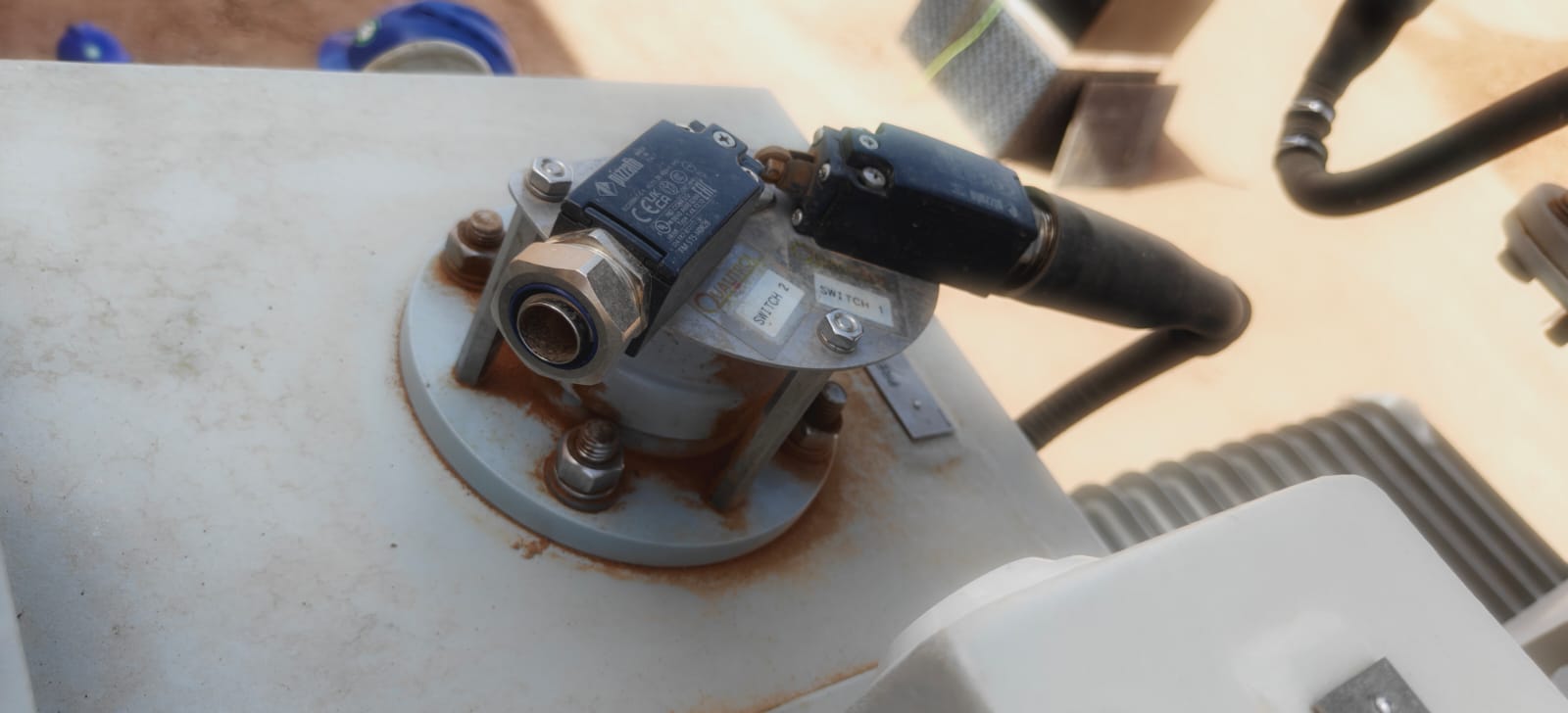
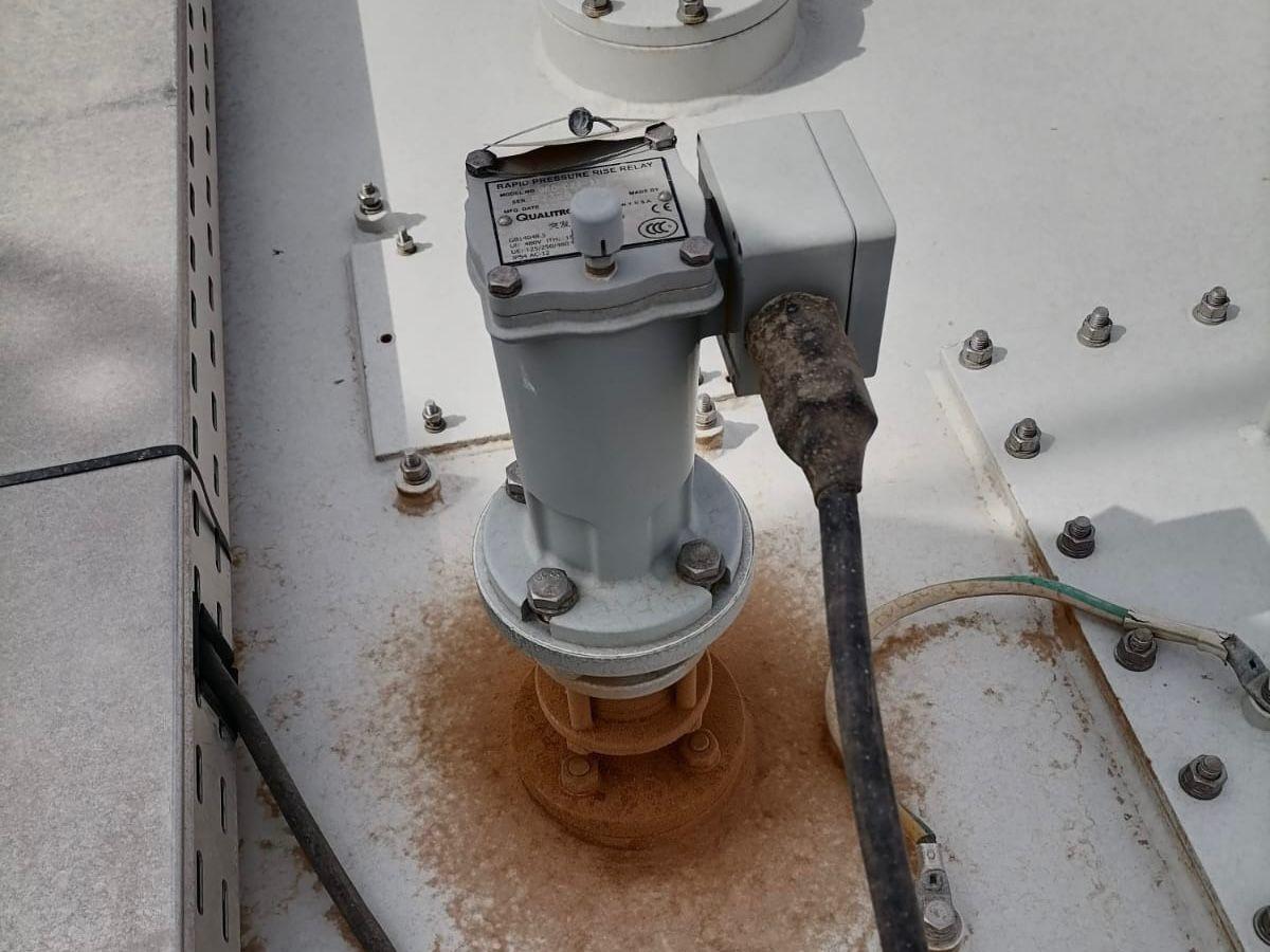
Gas-operated Buchholz relays, spring-loaded Pressure Relief Devices (PRDs) and sudden-pressure relays sit on elevated pipework where hardened flat gaskets and aged terminal-box O-rings seep steadily.
5. Main Tank Cover Rim & Inspection Manholes
Bolted bell-tank flanges and oval handhole covers stretch over metres of perimeter; uneven bolt torque or spliced gasket corners let oil weep across the tank rib stiffeners.
6. On-Load Tap Changer (OLTC) Diverter Head & Shafts
Frequent tap operations generate switching pressure spikes and carbonised oil inside the OLTC compartment, stressing head-cover O-rings, bevel-gear drive-shaft lip seals and oil-surge relay unions.
Beyond those primary six zones, five secondary points account for the remaining chronic drips we remediate during refinery GSU transformer turnarounds: (7) Conservator end-plates, magnetic oil level gauges (MOG) and air-cell breather piping, which sit highest in the sun; (8) Bottom drain, filter-press and oil-sampling valves, where uncapped brass plugs drip after annual DGA sampling; (9) Winding and oil temperature pocket wells and capillary glands; (10) Marshalling-box cable-entry glands and CT secondary terminal plates, where oil wicks right inside control wiring conduits if internal barrier studs loosen; and (11) Tank baseplate corner welds, especially on transformers that experienced rough jacking or uneven skid support before rigging.
Choosing the right elastomer and knowing when temporary patches fail
One of the most expensive mistakes in substation maintenance is stripping down a drained 100 MVA transformer, spending four days on crane rigging and vacuum equipment, and bolting it back together with cheap sheet gasket cut with a utility knife in a site workshop. Flat-cut gaskets without controlled compression stops extrude sideways when bolted up, relax under thermal load within two summers, and put you right back on the shutdown list.
Proper seal engineering matches both the elastomer compound and the groove geometry to the operating temperature and fluid chemistry. High-acrylonitrile Nitrile (NBR, 70 Shore A) remains an industry workhorse for standard mineral-oil flanges up to 100 °C, provided it is one-piece moulded or factory vulcanised at scarf joints and compressed strictly to twenty-five to thirty percent of its original thickness using metal limiter rings or machined O-ring grooves. Where turret covers, bushing top caps or refinery units run hotter—or where synthetic/natural ester fluids are specified—fluorocarbon elastomer (FKM / Viton) handles continuous temperatures well past 150 °C with minimal compression set.
For flat-faced radiator butterfly valves and older un-grooved manhole covers, high-density nitrile-bonded cork-elastomer with controlled compressibility can accommodate minor flange waviness, but only if bolt spacing is close enough and torque is applied in a calibrated star pattern across three incremental passes (thirty, seventy and one hundred percent of target torque, followed by a final stabilisation check four hours later).
What about cold-applied epoxy putties? In a pinch before a planned outage, a mechanical band clamp can temporarily contain a drip, whereas smearing two-part cold epoxy over an oil-wet radiator fin crack always fails: hot mineral oil penetrates weld porosity under head pressure and pops the rigid patch off as the panel flexes. When a pressed-steel radiator weld cracks, the lasting cure is closing the top and bottom isolation butterfly valves, blank-flanging that bank, and sending it to a clean shop for oil-free TIG welding and pneumatic pressure testing—or replacing the bank outright while our NDT inspection specialists dye-penetrant check adjacent header welds.
| Leak Location | Typical Root Cause in KSA | Permanent Engineering Fix | Target Seal Material & Proof Check |
|---|---|---|---|
| HV / LV Bushing Flange & Top Cap | Thermal baking at turret top + uneven stud pull-down | De-energise, lower oil below turret, dress flange face, renew top & base seals | One-piece moulded FKM (Viton) or high-ACN NBR O-ring; star-pattern torque |
| Radiator Header & Butterfly Valve | Compression-set flat gasket + coastal crevice rust | Crane-lift radiator bank, machine/clean seating faces, overhaul valve stem O-rings | OEM-profile NBR/FKM with compression limiter + 24-hr dry N2 hold |
| Radiator Cooling Fin Seam Weld | Fan-induced fatigue cracking on thin 1.2 mm steel | Isolate & blank bank, remove to shop for purged TIG weld or bank replacement | Shop hydro/pneumatic pressure test at 1.5× operating head before re-hanging |
| Buchholz Relay, PRD & MOG Flanges | UV/heat aging on upper pipework + cable gland seepage | Replace complete gasket kit & barrier terminal O-rings; functionally test trip contacts | FKM or high-grade NBR + relay trip prove-out via testing crew |
| Drain & Oil Sampling Valves | Dry stem packing + missing captive blanking plug | Repack/replace valve under vacuum lock or oil transfer; install brass gasketed cap | PTFE/FKM stem seals + metal-seated pressure dust cap |
How a zero-contamination transformer leak overhaul is executed in the field
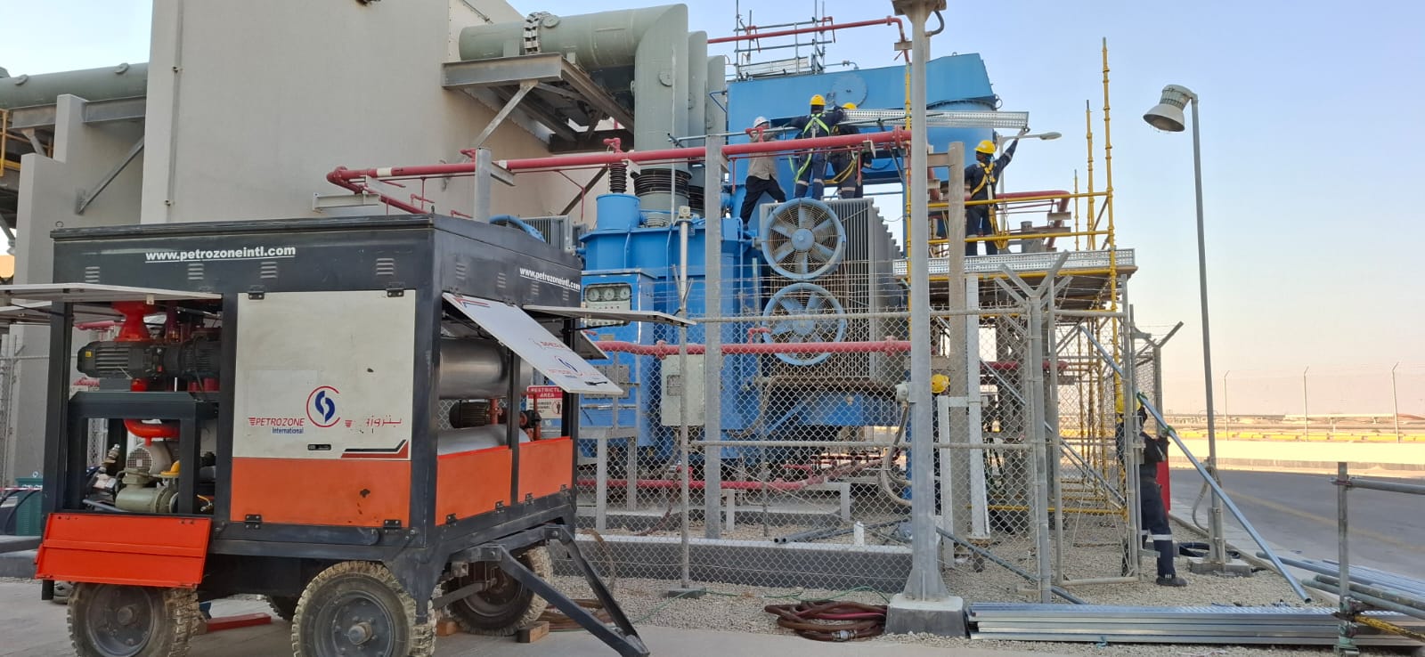
Opening a large power transformer in the middle of an operating petrochemical complex or utility switchyard carries serious risk if moisture control and rigging discipline slip for even an hour. Cellulose winding insulation begins absorbing atmospheric humidity the moment it is exposed to ambient air. On major overhauls, our crews coordinate rigging, closed-loop oil storage, gasket replacement and electrical proof-testing under one unified testing and commissioning quality plan so tank exposure time stays strictly bounded.
First comes isolation, earthing and baseline oil sampling. Before draining a single litre, we draw bottom and OLTC syringes for baseline Dissolved Gas Analysis (DGA), Breakdown Voltage (BDV per IEC 60156) and Karl Fischer moisture (ASTM D1533). That baseline tells us whether the leak has already dragged moisture or atmospheric gases into the active part, dictating how many hot-oil vacuum dehydration passes will be required before return to service.
Second, oil is transferred through dedicated, pre-flushed hoses into clean, sealed steel storage tanks fitted with silica-gel desiccant breathers—never open drums or uncleaned road tankers. While oil is safely held in closed-loop storage, positive dry-air or dry-nitrogen purge keeps internal core-and-coil humidity below safe dew-point limits whenever manholes or bushing turrets are opened. Where heavy radiator banks or 230 kV bushings must be lifted off the tank, certified riggers from our lifting and NDT division establish exclusion zones, verify crane outrigger bearing pressures and control taglines near fragile porcelain sheds.
Third, every exposed steel flange face is cleaned back to bright metal, checked with a straightedge for bolt-ear distortion, and fitted with dimensionally verified OEM gaskets. Where vendor-supplied replacement radiators, valves or bushings are installed, our Aramco-approved vendor inspection team can witness factory dimensional and pressure tests ahead of shutdown so nothing arrives at site with mismatched bolt circles.
Fourth—and this step separates lasting repairs from repeat leaks—we prove the dry tank before oil ever comes back in, or immediately upon vacuum completion. Pulling deep vacuum below 1 mbar (down to 0.1 mbar on high-voltage units) removes trapped air pockets from winding ducts and tests vacuum tightness. Oil is then heated, degassed through multi-stage high-vacuum purification plants and vacuum-filled slowly from the bottom manifold. Once full, we pressurise the headspace with dry nitrogen to the manufacturer’s test pressure (typically 0.25 to 0.35 bar gauge) and hold it for twenty-four hours while logging pressure versus ambient temperature and soap-checking every disturbed bolt circle. Zero drop after temperature compensation means zero leaks.
Finally, after the mandatory oil settling period (twelve to twenty-four hours depending on voltage class so micro-bubbles clear from high-stress winding wedges), our commissioning engineers run Insulation Resistance, Polarization Index, Capacitance and Tan Delta, Winding Resistance and Turns Ratio checks—the same discipline we pair with medium-voltage switchgear preventive maintenance and online UHF partial discharge monitoring on downstream substation bays. If you have a weeping bushing, radiator header or PRD on a critical unit, explore more field reports on our engineering blogs hub or request a technical site survey from our Al-Khobar power team.
More from our engineers & field teams
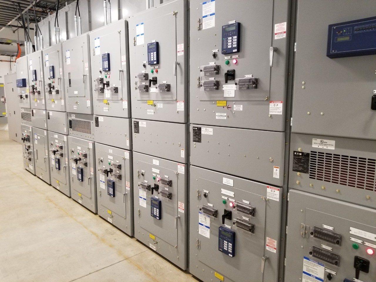
UHF partial discharge monitoring: 24/7 switchgear protection in Saudi Arabia
How continuous UHF sensing detects early insulation defects inside medium- and high-voltage switchgear before failure occurs.
Read article →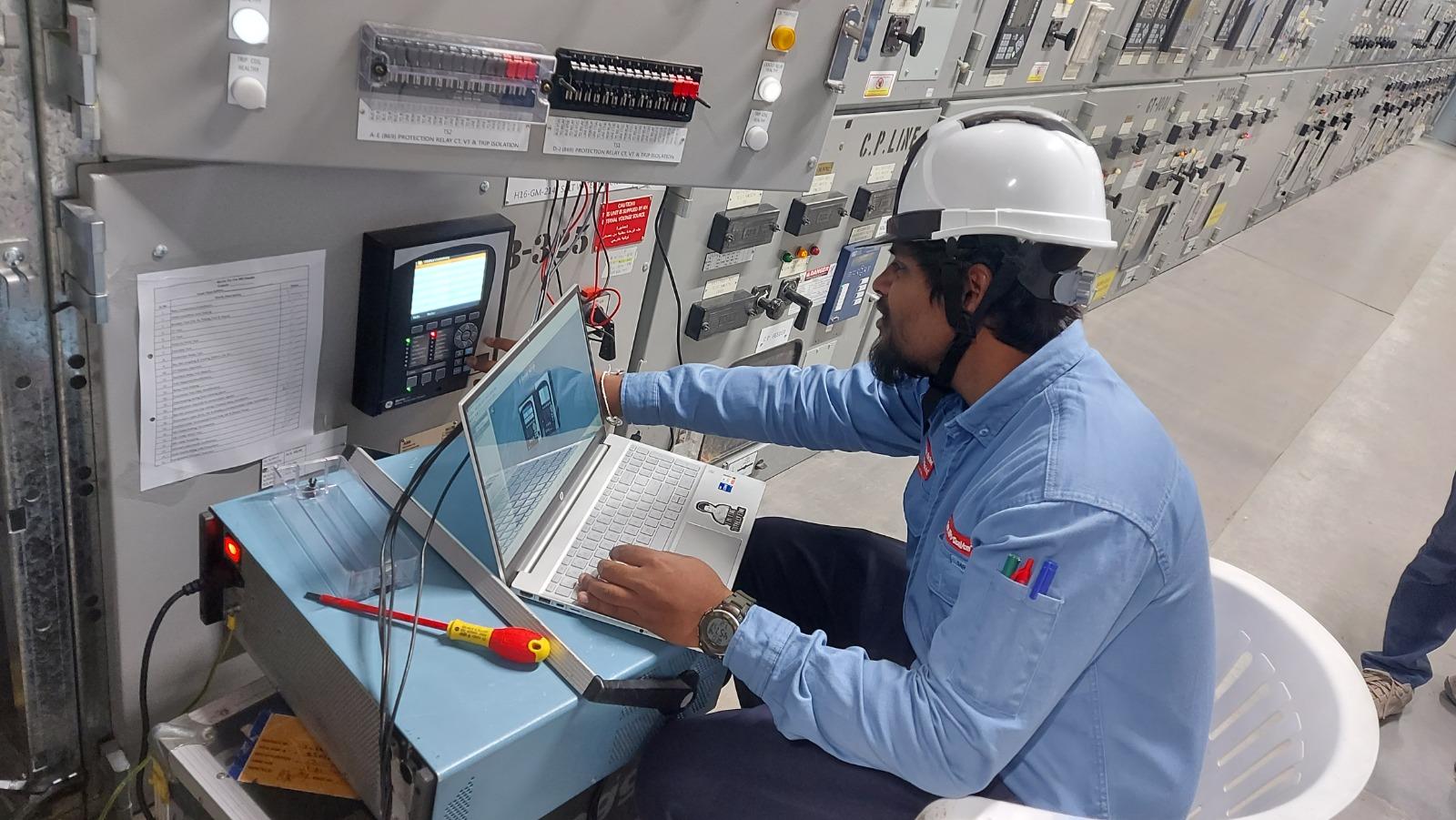
Preventive maintenance of medium-voltage switchgear: field guide
Inspection intervals, diagnostic testing checks and practical maintenance procedures to prevent unplanned substation outages.
Read article →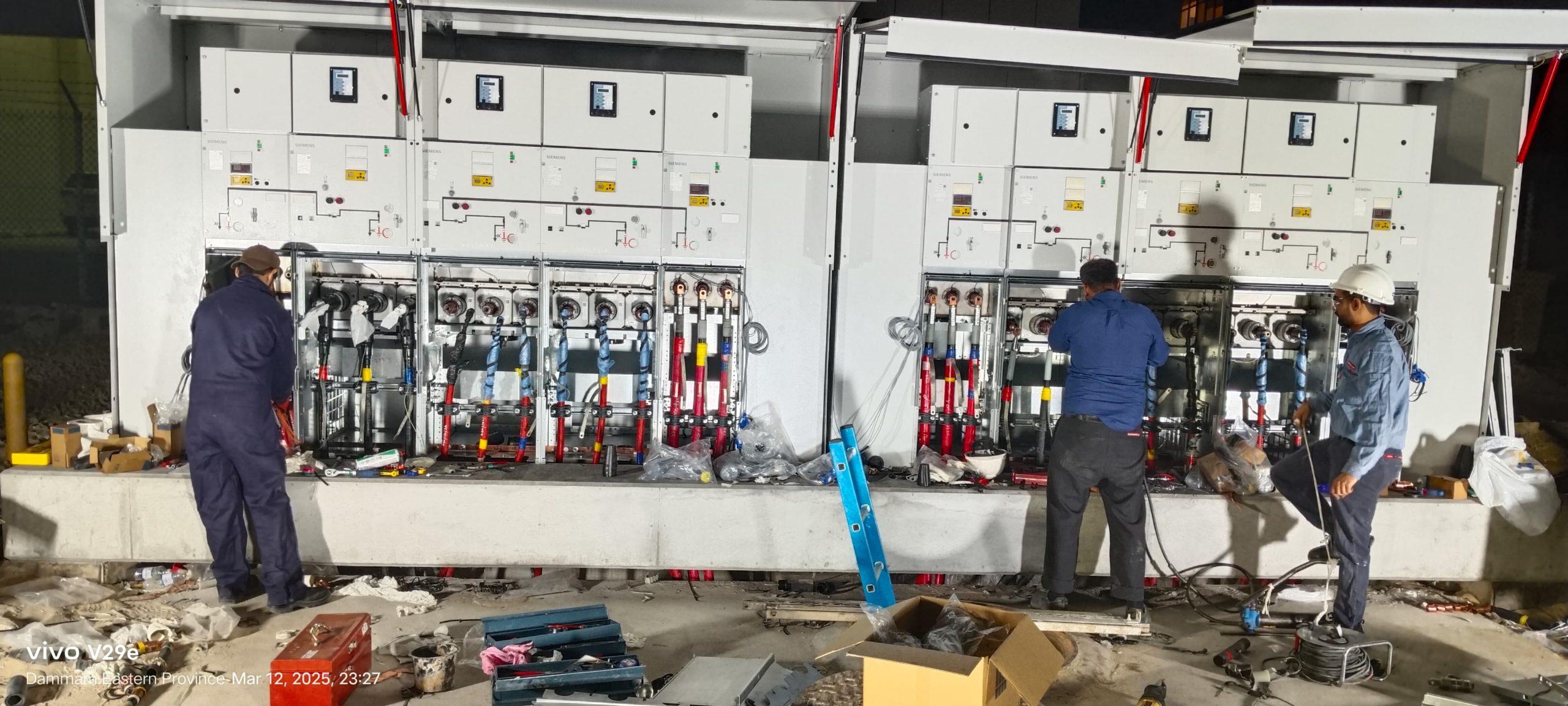
A 72-hour turnaround for RMU replacement & MV cable termination
Day-and-night replacement of an aging ring main unit, medium-voltage cable termination and commissioning completed within a strict 72-hour window in Saudi Arabia.
Read article →Planning a project? Talk to the right division.
Send us the scope, location and timeline. We will reply with the right team and a quote.