
UHF partial discharge monitoring: 24/7 switchgear protection in Saudi Arabia
Why calendar-based inspections miss internal insulation breakdown in 13.8 kV and 33 kV metal-clad switchgear—and how continuous 400–1600 MHz UHF sensing catches defects months before arc-flash failure.
Why switchgear passes an annual shutdown test and still flashes over six months later
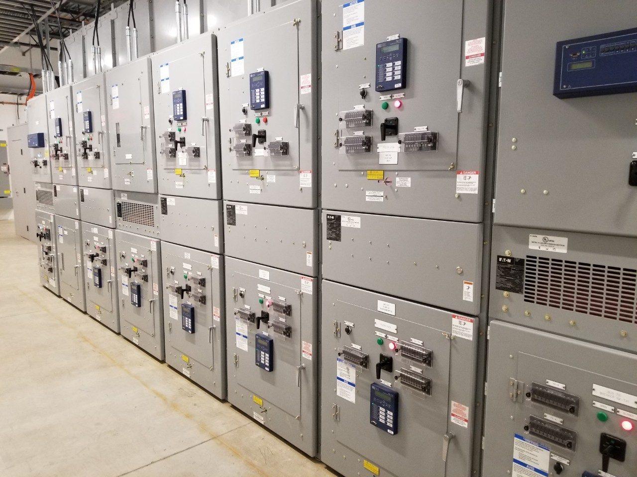
Ask any refinery electrical superintendent in Jubail or Yanbu what keeps them awake during peak summer load, and arc-flash inside a main 13.8 kV or 33 kV intake board sits near the top of the list. Unlike a rotating pump or compressor that vibrates, runs hot on its bearings and gives weeks of audible warning before seizing, medium-voltage switchgear stands silent in an air-conditioned substation room right up to the millisecond an insulation path breaks down phase-to-earth or phase-to-phase.
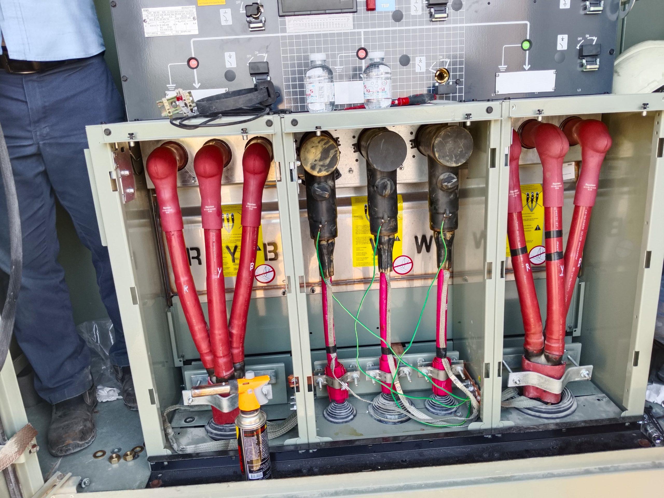
Roughly eighty to eighty-five percent of disruptive medium- and high-voltage switchgear failures originate from insulation degradation—and almost all of that degradation announces itself first as Partial Discharge (PD). Partial discharge is a localised dielectric breakdown bridging only a tiny fraction of the insulation between conductors: a microscopic gas bubble trapped inside a cast-resin current transformer during manufacture, a knife-nick left on XLPE cable insulation under a stress-control tube, or conductive salt-dust tracking across an epoxy spout bushing.
Because the rest of the insulation barrier remains intact, leakage current is measured in picocoulombs rather than amperes. Overcurrent and earth-fault relays see nothing. Even infrared thermography through crystal viewing ports misses early internal PD completely, because picocoulomb discharges generate negligible bulk resistive heating until the final days before catastrophic flashover.
Traditional maintenance tries to catch these defects with handheld Transient Earth Voltage (TEV) and ultrasonic surveys every six or twelve months, or with offline high-voltage tests during a three-year turnaround. The catch is that PD in industrial substations is heavily load-, voltage- and humidity-dependent. A switchgear cable compartment inspected on a cool, dry February afternoon at fifty percent feeder load can read dead quiet on a handheld meter—then ignite vigorous surface tracking in August when substation HVAC struggles, relative humidity rises past sixty-five percent, and compressor motors run flat out. That gap between snapshots is why plants are moving to permanent 24/7 online partial discharge monitoring across their critical lineups.
Inside the 60 Hz cycle: how a microscopic cavity turns into an electrical tree
Understanding why Ultra-High Frequency (UHF) sensing works so well starts with what happens inside solid epoxy or XLPE insulation on Saudi Arabia’s 60 Hz power grid. Permittivity in solid cast resin or cross-linked polyethylene is roughly four times higher than permittivity in air. Whenever a tiny air pocket exists inside solid insulation—or where thermal cycling delaminates resin from an embedded copper busbar—electric field stress concentrates inside that low-permittivity gas gap.
Once local field stress across the void exceeds the breakdown strength of air (around 3 kV/mm at atmospheric pressure), a tiny spark jumps across the cavity twice every power cycle, or 120 times every second on a 60 Hz bus. Each sub-nanosecond electron avalanche bombards the organic polymer wall with ultraviolet photons, ozone, nitric acid (when moisture is present) and intense pinpoint heat. Over months, smooth cavity walls pit and carbonise. Because carbon conducts electricity, those pits sharpen the local electric field tip like a microscopic needle, driving hollow, branching carbonised channels—known as electrical trees—deeper through the solid dielectric.
In the field, we see switchgear insulation breakdown unfold across four distinct operational stages. Catching a bay in Stage 1 or Stage 2 turns an unplanned emergency switchgear rebuild into a calm, two-hour component swap during a scheduled medium-voltage switchgear preventive maintenance window.
Stage 1 · Internal Cavity Ignition (50–250 pC)
Micro-voids inside epoxy CTs, VTs, spout bushings or cable stress cones begin sparking on voltage peaks. Zero heat, zero odour, zero ultrasonic leak outside sealed housings—but clear UHF electromagnetic pulses radiate inside the metal cubicle, giving 12 to 24 months of planning lead time.
Stage 2 · Delamination & Tree Initiation (250–1,000 pC)
Repeated chemical and ionic bombardment erodes void walls into conductive carbon pits. Phase-Resolved Partial Discharge (PRPD) clusters widen across the first and third quadrants of the 60 Hz sine wave. Lead time typically spans 6 to 12 months.
Stage 3 · Surface Tracking & Ozone Formation (1,000–5,000+ pC)
Where discharges break out onto humid or dust-contaminated barrier surfaces—especially around poorly dressed MV cable terminations—nitric acid crystals (‘white powder’) form and carbon tracks creep visibly across insulation skirts. Failure can occur within 2 to 12 weeks.
Stage 4 · Full Dielectric Flashover & Arc Fault
The remaining healthy insulation bridge collapses during a motor-starting transient, capacitor-bank switch or lightning surge. A multi-kiloamp arc vaporises copper within milliseconds, destroying panels unless cleared instantly.
Why 400–1600 MHz UHF excels inside noisy industrial plants
Every sub-nanosecond partial discharge current pulse has a rise time faster than one nanosecond. By Fourier physics, a pulse that steep radiates electromagnetic energy well past one gigahertz. Inside metal-enclosed AIS or GIS switchgear, the grounded sheet-steel walls of the circuit-breaker, busbar and cable compartments act like resonant waveguide cavities—trapping internal UHF waves so they bounce cleanly into an internal compartment antenna while shielding that antenna from outside radio noise.
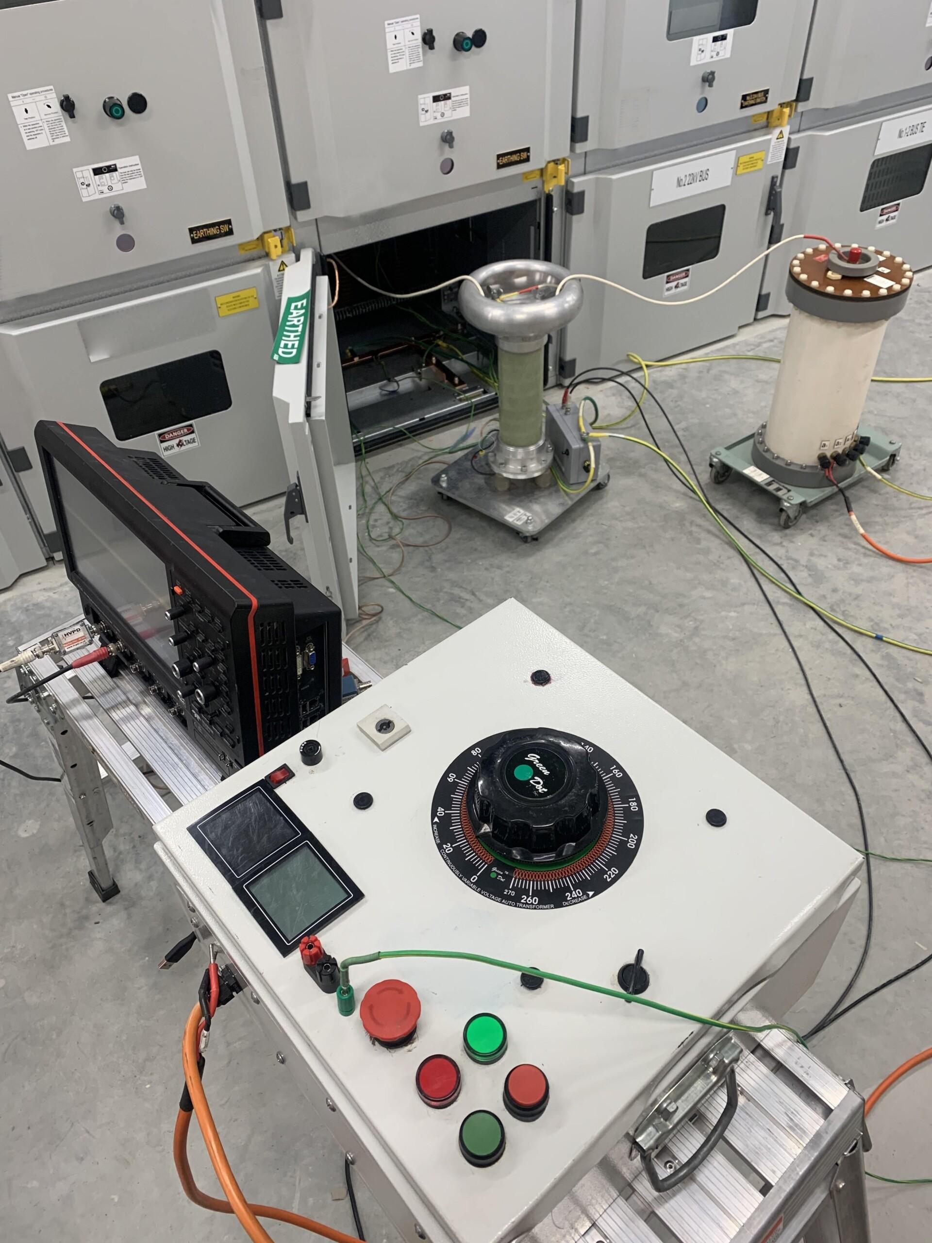
Compare that behaviour with lower-frequency methods in a petrochemical plant full of variable-frequency drives (VFDs), thyristor rectifiers, UPS inverters and welding machines. Conventional IEC 60270 coupling-capacitor measurements operate below 1 MHz, right where VFD switching harmonics saturate the noise floor unless the feeder is taken completely offline and energised from a clean test set. Acoustic / ultrasonic microphones (20–40 kHz) work well for open-air corona or surface tracking where an air gap exists line-of-sight to the sensor, yet solid cast-resin CTs and sealed plug-in T-cones attenuate acoustic waves completely—meaning an internal epoxy void can chew halfway through a current transformer before a single ultrasonic decibel escapes.
Handheld TEV probes (typically 3–100 MHz) capacitively sense skin-effect voltage pulses on the outside of metal doors, which makes them handy for quick screening walkdowns, but external corona on overhead yard gantries, fluorescent lighting ballasts and nearby motor drives frequently trigger false TEV alarms that undermine operator trust. By moving detection up into the 400 to 1600 MHz UHF band and dividing the spectrum across multi-band tuned RF channels, permanent UHF sensors step cleanly above VFD and power-electronic switching noise while capturing deep internal void discharges that acoustic sensors never hear.
| Diagnostic Technique | Operating Frequency | Internal Cast-Resin & Cable Void Sensitivity | Outage Required? | Industrial VFD / Rectifier Noise Immunity |
|---|---|---|---|---|
| Permanent Online UHF Sensing | 400 – 1600 MHz | Very High — captures deep internal voids & surface tracking | None (24/7 Live) | Excellent inside grounded metal-clad compartments |
| Fiber-Optic Contact Thermal Sensing | Optical GaAs / Fluorescent | Detects loose bolted joints (not early cold PD) | None (24/7 Live) | 100% immune to EMI and high voltage |
| Handheld TEV Door Survey | 3 – 100 MHz | Moderate — weaker on deep solid-dielectric cavities | None (Snapshot only) | Prone to false positives from external switching noise |
| Airborne / Contact Ultrasonic | 20 – 150 kHz | Low for internal voids; strong on open surface corona | None (Snapshot only) | Blocked by gasketed doors & solid epoxy resin |
| Offline IEC 60270 HV Test | 40 – 800 kHz | Very High — calibrated picocoulomb lab reference | Full Bus Outage | Requires isolated low-noise HV power source |
Pairing UHF partial discharge with 24/7 busbar temperature monitoring
Partial discharge accounts for dielectric breakdown, while high-resistance bolted joints account for the rest of switchgear thermal failures. A loose M12 busbar splice, a fatigued breaker tulip finger or an under-torqued cable lug heats up purely through I²R losses without generating partial discharge until surrounding insulation chars. Conversely, an internal epoxy void generates intense partial discharge without raising busbar copper temperature by even half a degree.
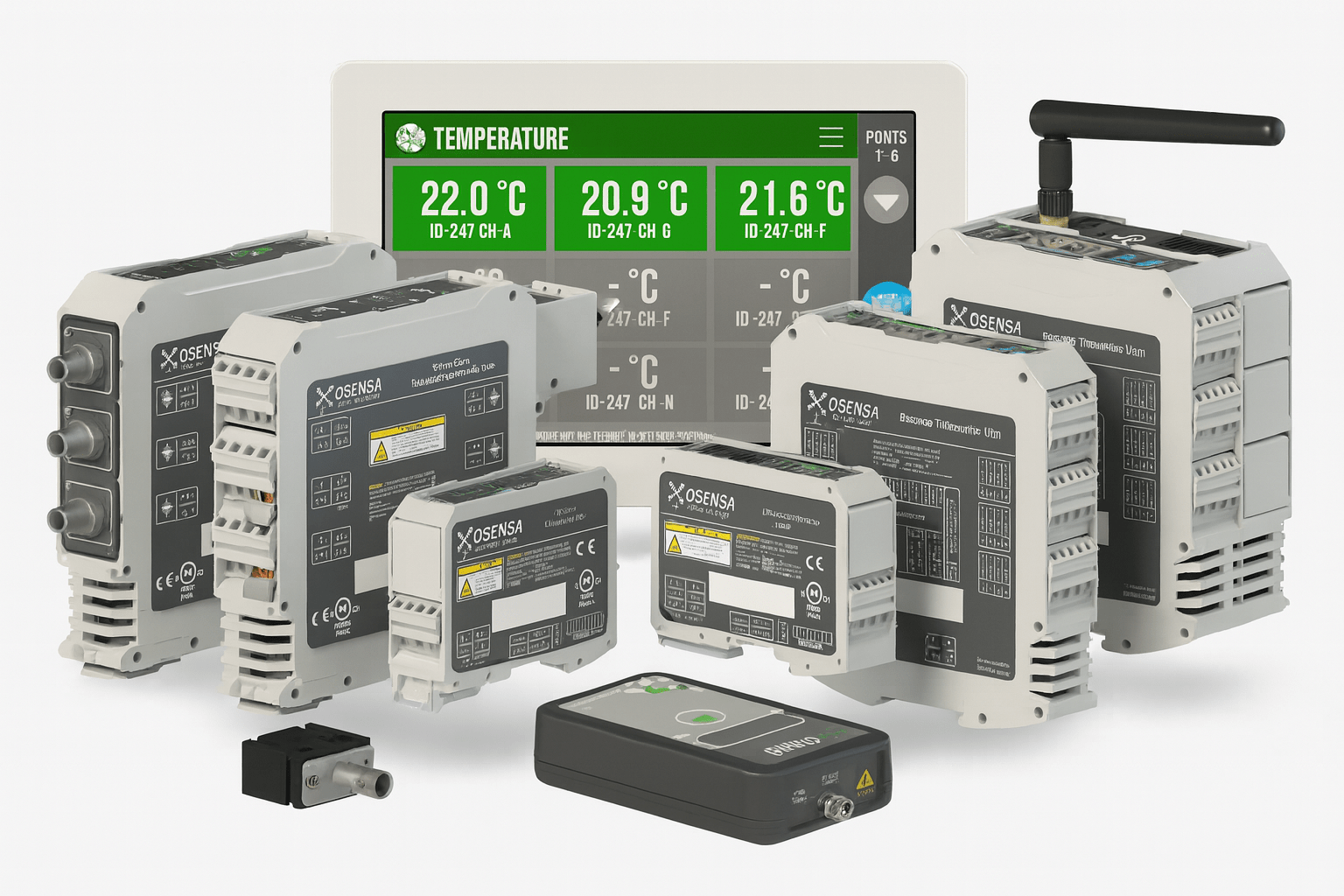
That is why our most resilient 24/7 switchgear temperature and PD monitoring installations combine both measurements inside the same cubicle architecture. Passive, dielectric fiber-optic temperature probes bolt directly onto live 13.8 kV or 33 kV breaker spouts, busbar risers and cable lugs—requiring zero batteries inside the high-voltage zone and introducing zero creepage reduction—while compact wideband UHF sensors mount safely on the grounded steel wall of the cable/CT compartment.
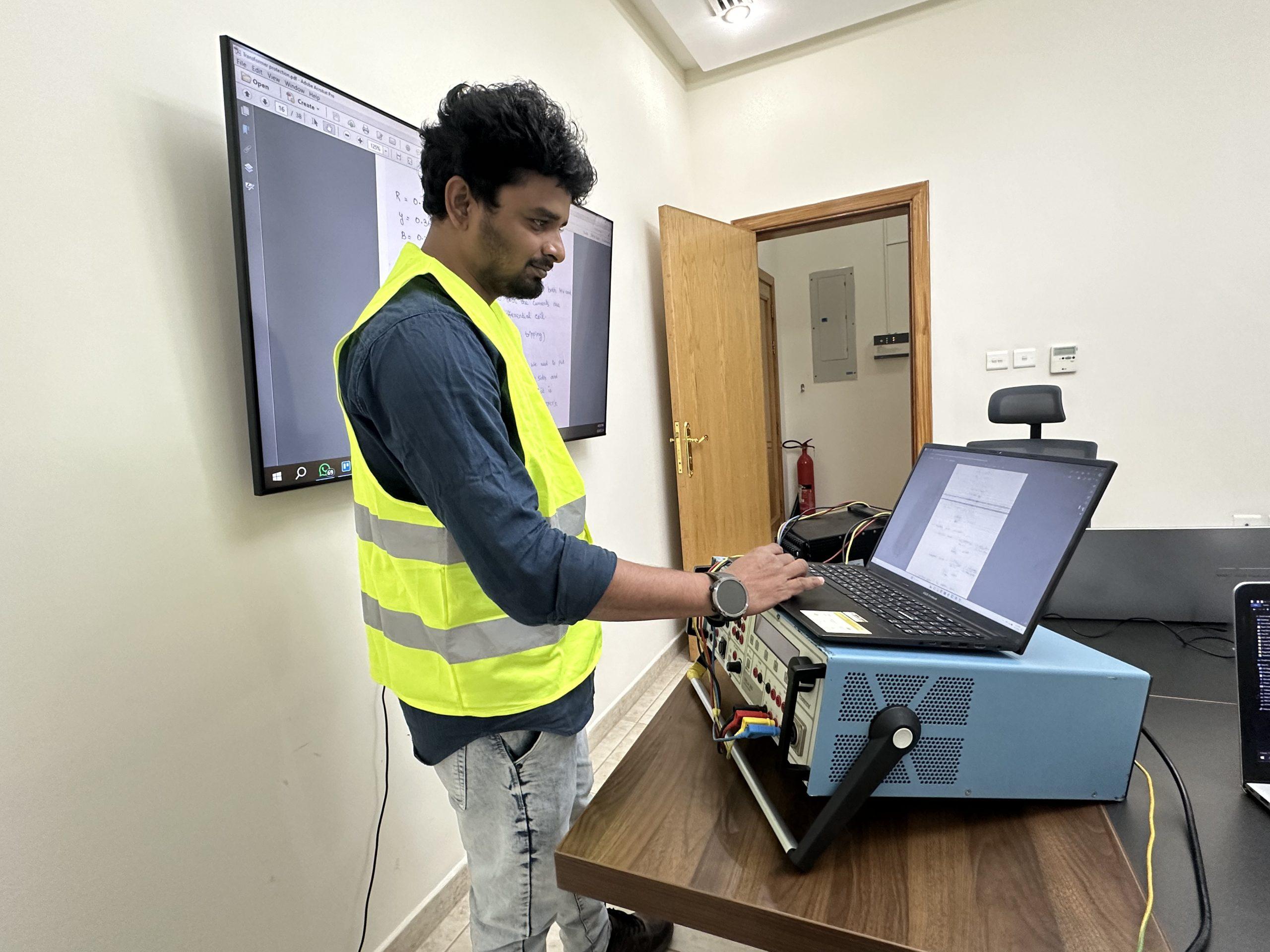
During our rapid RMU replacement and MV cable termination turnarounds, pre-engineering sensor mounting brackets and routing armored fiber pigtails into the low-voltage relay chamber takes very little extra outage time. Once landed on DIN-rail transmitters in the LV niche, real-time PD pulse magnitude, pulse repetition rate and per-phase conductor temperatures stream straight to a local colour touchscreen HMI on the substation wall and upstream over Modbus TCP/RTU or IEC 61850 to the plant DCS or substation automation historian.
Where to install sensors first—and how to commission alarm thresholds without nuisance trips
Few maintenance budgets cover instrumenting all two hundred cubicles across an entire petrochemical complex in a single fiscal year, nor do they need to. Smart reliability teams prioritise switchgear bays by consequence of failure and insulation stress: main 33 kV and 13.8 kV grid incomers, bus-tie breakers, generator incomers downstream of critical power and GSU transformers, large captive VFD compressor feeders subject to steep dV/dt voltage reflections, and older lineups where electrical equipment retrofitting is extending panel life.
Sensor density inside each bay follows field geometry. On standard single-busbar metal-clad panels (such as ABB UniGear ZS1, Siemens NXAIR or Schneider MCset), one UHF antenna positioned in the rear cable-and-CT compartment has clear electromagnetic coupling to the three-phase medium-voltage cable terminations, current transformers and lower spout bushings—statistically where over seventy percent of switchgear PD starts. On double-busbar 33 kV panels or long bus-duct runs, adding a second sensor in the upper busbar chamber ensures full coverage across segregating steel partitions.
Commissioning is where engineering judgement pays off. Rather than punching factory-default alarm setpoints into the HMI and walking away, our testing and commissioning engineers run a seven-to-fourteen-day dynamic baselining period across normal day/night plant switching cycles. We verify RF noise-gating channels against nearby VFD harmonics, inject calibrated reference pulses into each cubicle to confirm antenna sensitivity, and configure two-tier alerting: an early Advisory notification when sustained PD rises 6 to 10 dB above baseline for more than forty-eight hours, and a Critical maintenance alarm when both pulse amplitude and repetition rate climb aggressively.
When an advisory triggers, Petrozone’s diagnostic team doesn’t ask operations to trip the plant blind. We correlate the UHF trend with ambient substation humidity and feeder current, perform phase-resolved pattern classification (distinguishing internal symmetric cavity voids from asymmetric conductor-floating or surface-tracking signatures), and pinpoint the exact phase component so replacement CTs, bushings or termination kits are sitting in stores before the feeder is ever isolated. In practice, that difference is stark: an internal void inside a cast-resin CT produces symmetric ‘rabbit-ear’ clusters ahead of both positive and negative 60 Hz voltage peaks regardless of room humidity, whereas external surface tracking across a salt-filmed cable boot flares sharply whenever night-time relative humidity climbs and HVAC dampers cycle. Knowing which defect sits behind the steel door lets maintenance bring the exact spare kit, crane permit and cable jointer crew on the first outage.
Even on transformer-connected switchgear bays, pairing switchgear UHF data with transformer seal and DGA condition checks and high-voltage leak remediation gives reliability managers end-to-end visibility from incoming grid gantry to motor terminal box. Want to evaluate online UHF PD and fiber-optic thermal monitoring on a critical 13.8 kV or 33 kV board without taking an outage? Browse more field case studies on our technical articles page or speak directly with Petrozone’s predictive diagnostics engineers in Al-Khobar to arrange an on-site substation survey.
More from our engineers & field teams
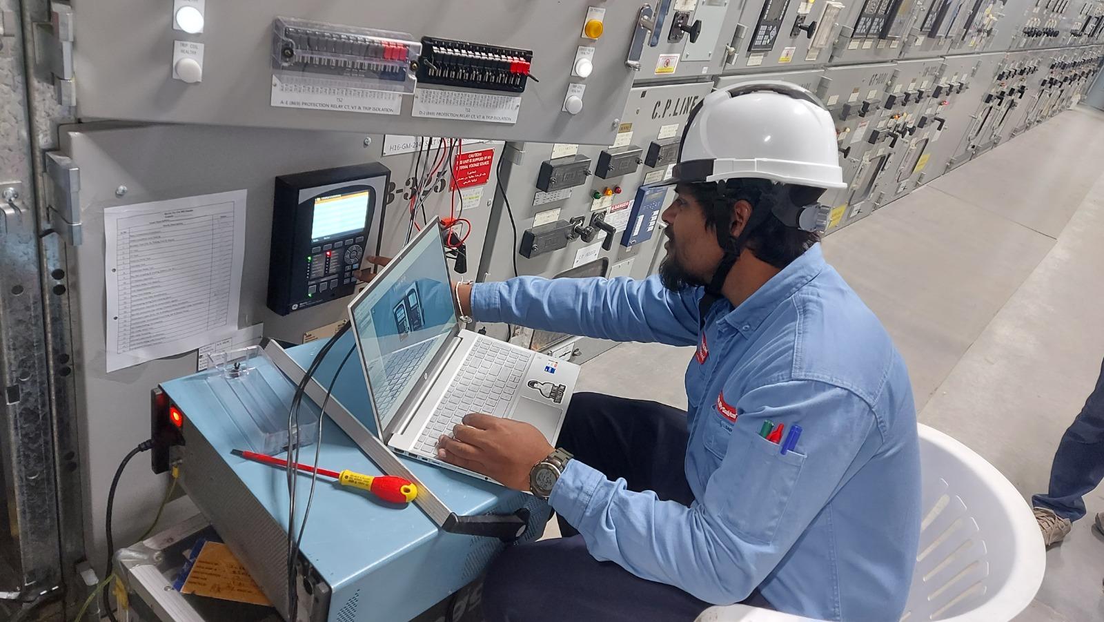
Preventive maintenance of medium-voltage switchgear: field guide
Inspection intervals, diagnostic testing checks and practical maintenance procedures to prevent unplanned substation outages.
Read article →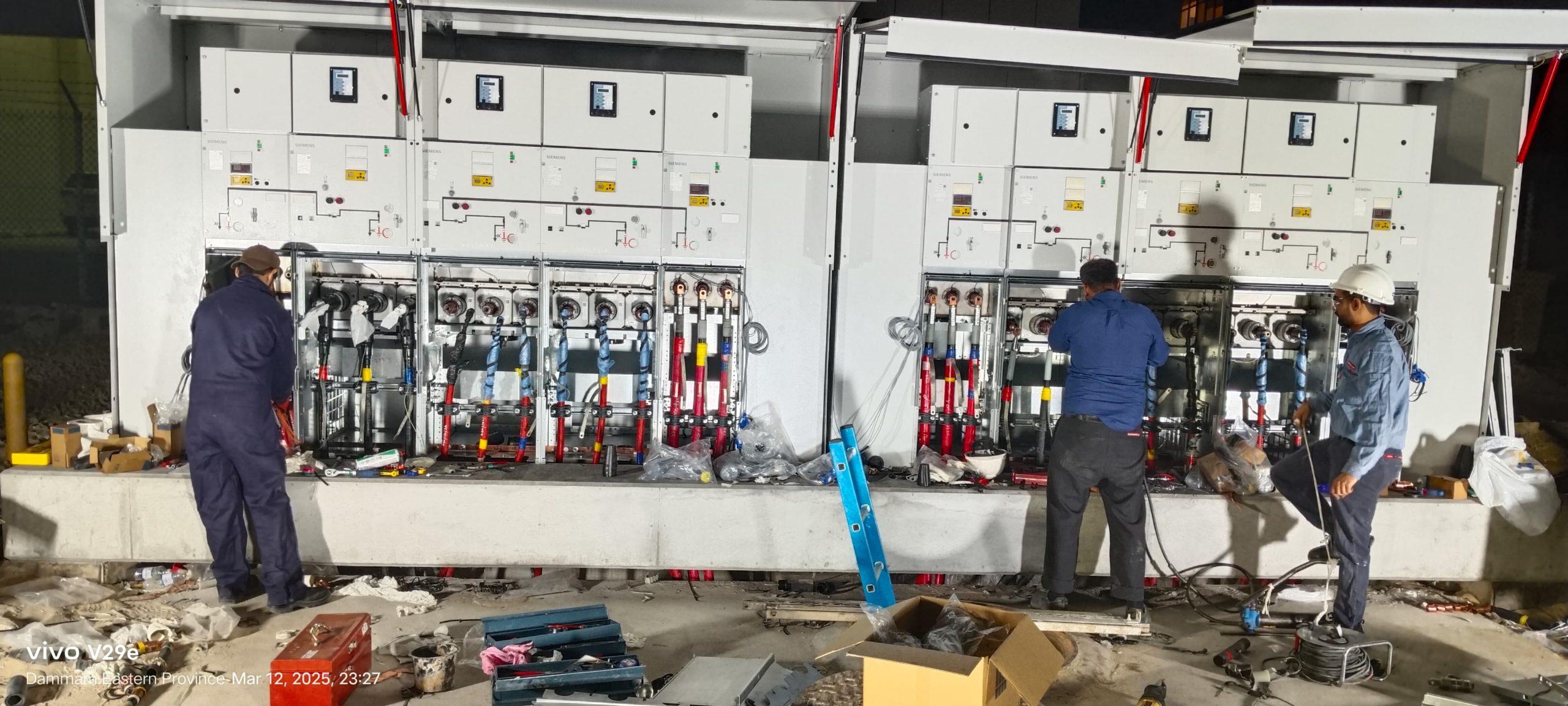
A 72-hour turnaround for RMU replacement & MV cable termination
Day-and-night replacement of an aging ring main unit, medium-voltage cable termination and commissioning completed within a strict 72-hour window in Saudi Arabia.
Read article →
Critical 220 MVA GSU transformer maintenance for leading Saudi refinery
High-precision turnaround maintenance, insulating oil treatment and diagnostic verification executed on schedule at a major refinery in Saudi Arabia.
Read article →Planning a project? Talk to the right division.
Send us the scope, location and timeline. We will reply with the right team and a quote.