
Preventive maintenance of medium-voltage switchgear: field guide
Field-tested shutdown procedures, diagnostic pass/fail benchmarks and practical maintenance intervals for 13.8 kV and 33 kV AIS, GIS and Ring Main Unit lineups across Saudi Arabia.
The dormant-duty problem on 13.8 kV and 33 kV industrial boards
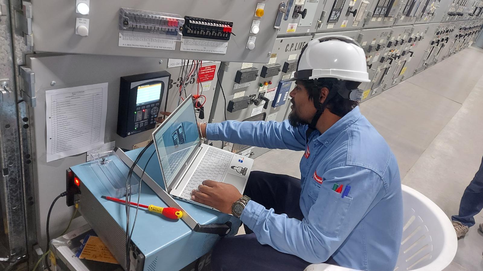
A medium-voltage circuit breaker has the strangest job in an industrial plant. Unlike a process compressor or feedwater pump that proves its mechanical health every minute it spins, an incomer or bus-tie breaker on a 13.8 kV petrochemical board might sit closed in the exact same position for twenty-four months straight. Then, at three in the morning during a summer lightning storm or a motor cable fault, that breaker has roughly fifty milliseconds—three cycles at 60 Hz—to unlatch a spring mechanism, accelerate moving contacts to full travel, extinguish a twenty-five-kiloamp arc, and isolate the fault before upstream transformers or busbars suffer catastrophic damage.
When a breaker fails to trip on command in Saudi Arabia, the post-mortem almost never points to a sudden manufacturing defect. Nine times out of ten, the root cause is something mundane that built up quietly over years of unexercised duty: lithium soap grease in the trip-latch roller that baked into sticky varnish under warm substation temperatures, fine desert dust packed onto shutter pivot pins, an open-circuited space heater that allowed coastal condensation on epoxy spouts, or a degraded station battery cell whose terminal voltage collapsed the instant the 110 V DC trip coil tried to pull.
Whether your substation runs air-insulated metal-clad panels (ABB UniGear ZS1, Siemens NXAIR, Schneider MCset, Eaton Power Xpert, GE Power/Vac), SF6 gas-insulated switchgear (Siemens 8DA10 / 8DB10, ABB ZX2) or compact distribution Ring Main Units, preventive maintenance has one overarching goal: proving that primary insulation, current-carrying joints, mechanical kinematics and secondary protection logic act together as a single reliable chain.
Across sixteen-plus years of substation testing and commissioning from Al-Khobar and Jubail to Yanbu and Riyadh, our field teams follow a disciplined shutdown methodology that catches mechanical sluggishness and electrical drift long before an emergency trip tests your luck.
What experienced engineers look for the minute cubicle doors open
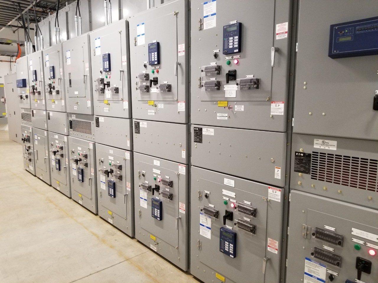
Good switchgear maintenance starts before anyone unrolls a test lead. Under Saudi Aramco SAES-P-119 and SEC substation safety rules, isolating a double-ended 13.8 kV or 33 kV switchboard requires strict Permit-to-Work (PTW) verification, racking out incoming and bus-section trucks to the disconnected position, proving dead on all three phases with a self-proving capacitive high-voltage live-line tester, applying integral fault-making earthing switches (never improvised jumper leads), and locking out remote SCADA closing circuits plus VT back-feed fuses.
Resist the urge to let helpers wipe down insulators immediately after opening the rear cable and busbar covers. That untouched dust layer is forensic evidence. Before touching a rag to anything, walk the open bays with a bright raking torch and an inspection mirror:
- White crystalline powder or chalky rings around cast-resin CTs, epoxy wall bushings or cable stress cones signal nitric-acid attack from sustained surface partial discharge combined with ambient humidity—a clear cue to evaluate continuous UHF partial discharge monitoring on that board.
- Greenish verdigris or darkpurple-brown oxide discolouration on silver-plated breaker tulip fingers, copper busbar risers or flexible laminations points to chronic overheating or hydrogen-sulphide (
H2S) corrosion common near sour-gas processing units and coastal wastewater plants. - Sticky amber residue on breaker operating linkages tells you the original factory grease has separated its base oil from its thickener; flushing old hardened grease out with approved solvent before applying fresh synthetic low-friction lubricant (such as Mobilgrease 28 or OEM-specified Klüber) is essential, because layering fresh grease over dried soap still leaves the latch slow.
- Dead panel anti-condensation heaters or mis-set hygrostats: Many operators turn heaters off in summer thinking Saudi heat makes them redundant, forgetting that heavily air-conditioned substation rooms chilled to 20 °C create instant condensation inside unventilated cable trenches whenever humid night air leaks up through unsealed floor ducts.
When cleaning primary insulation, ban compressed plant air—it blasts conductive dust deeper into breaker arc chutes and contaminates oil-wet air lines—and never use abrasive Scotch-Brite pads on epoxy resin or porcelain glaze, because micro-scratches trap moisture and trigger surface tracking. Use HEPA-filtered industrial vacuums followed by lint-free cloths lightly dampened with high-purity isopropyl alcohol (99% IPA), allowing full flash-off evaporation before any high-voltage insulation test.
Testing vacuum and SF6 circuit breakers beyond a simple open-close click
Pressing the mechanical ‘Push to Trip’ button on the front fascia proves the main shaft turns, and very little else. To verify that a 13.8 kV vacuum breaker or 33 kV SF6 breaker will interrupt fault current safely, our electrical division field engineers run four quantitative measurements on every withdrawable truck or fixed pole assembly.
First is static contact resistance (Ductor / micro-ohm testing) injected at 100 A or 200 A DC across each racked-out pole, and then repeated across the complete primary path (upper busbar spout through tulip fingers, vacuum interrupter, lower tulip fingers and CT bar) with the truck racked in. Measuring both isolates whether high resistance sits inside worn vacuum bottle butt-contacts or outside on oxidized silver-plated cluster fingers and weak garter springs. Any phase reading more than twenty percent higher than its sister phases—even if technically below the OEM ceiling—gets stripped, cleaned and re-tensioned on the spot.
Second is mechanical travel, coil current and timing analysis. Connecting a multi-channel breaker analyser records exact opening time (typically 30–45 ms), closing time (50–75 ms), close-open (C-O) trip-free time, contact bounce duration (< 2 ms on vacuum bottles to prevent contact welding), and inter-pole simultaneity (< 2 ms phase spread). Equally revealing is the DC current waveform through Trip Coil 1, Trip Coil 2 and the Closing Coil: a flattened or delayed current dip on the coil signature reveals a dry plunger sleeve or binding armature weeks before the coil burns out or fails to unlatch at minimum 70% DC battery voltage.
Third is interrupter dielectric integrity. On vacuum circuit breakers, a micro-leak in the stainless-steel bellows lets atmospheric air enter the bottle without any external sign; a dedicated AC/DC vacuum bottle integrity high-potential test across open contacts verifies the interrupter has not gone ‘flat’. On SF6 gas breakers and GIS bays, we verify gas pressure-temperature compensation switches, test alarm and lockout contacts on the density monitor, check SF6 purity (> 97%) and moisture dew point, and scan flange seals with a halogen/SF6 sniffer.
Fourth, when panels exceed twenty to twenty-five years and spare mechanical latches or legacy minimum-oil / obsolete SF6 trucks are no longer supported by OEMs, full circuit breaker retrofitting—installing modern type-tested vacuum roll-in replacement trucks inside existing healthy steel cubicles—restores brand-new fault-clearing performance without disturbing civil trenches or field power cables.
1. Static & Dynamic Contact Resistance
100–200 A DC micro-ohm test on isolated poles (< 35–50 µΩ typical) plus full spout-to-spout racked-in loop check (< 15% phase-to-phase delta).
2. Close / Open / C-O Timing & Bounce
Millisecond timing across all three poles, < 2 ms vacuum bounce limit, spring charging motor current/time, and minimum-voltage trip prove-out at 70% Vdc.
3. Insulation Resistance & Power-Frequency Withstand
5 kV DC Megger phase-to-earth and phase-to-phase (1 min / PI check), plus 1-minute AC high-pot / vacuum integrity check per IEC 62271-100.
4. Mechanical Interlocks & Racking Gear
Mandatory verification that trucks cannot rack in/out with breaker closed, earthing switches cannot close onto live feeders, and shutters lock positively.
Torque discipline on main busbars and proving CTs, VTs and cable terminations
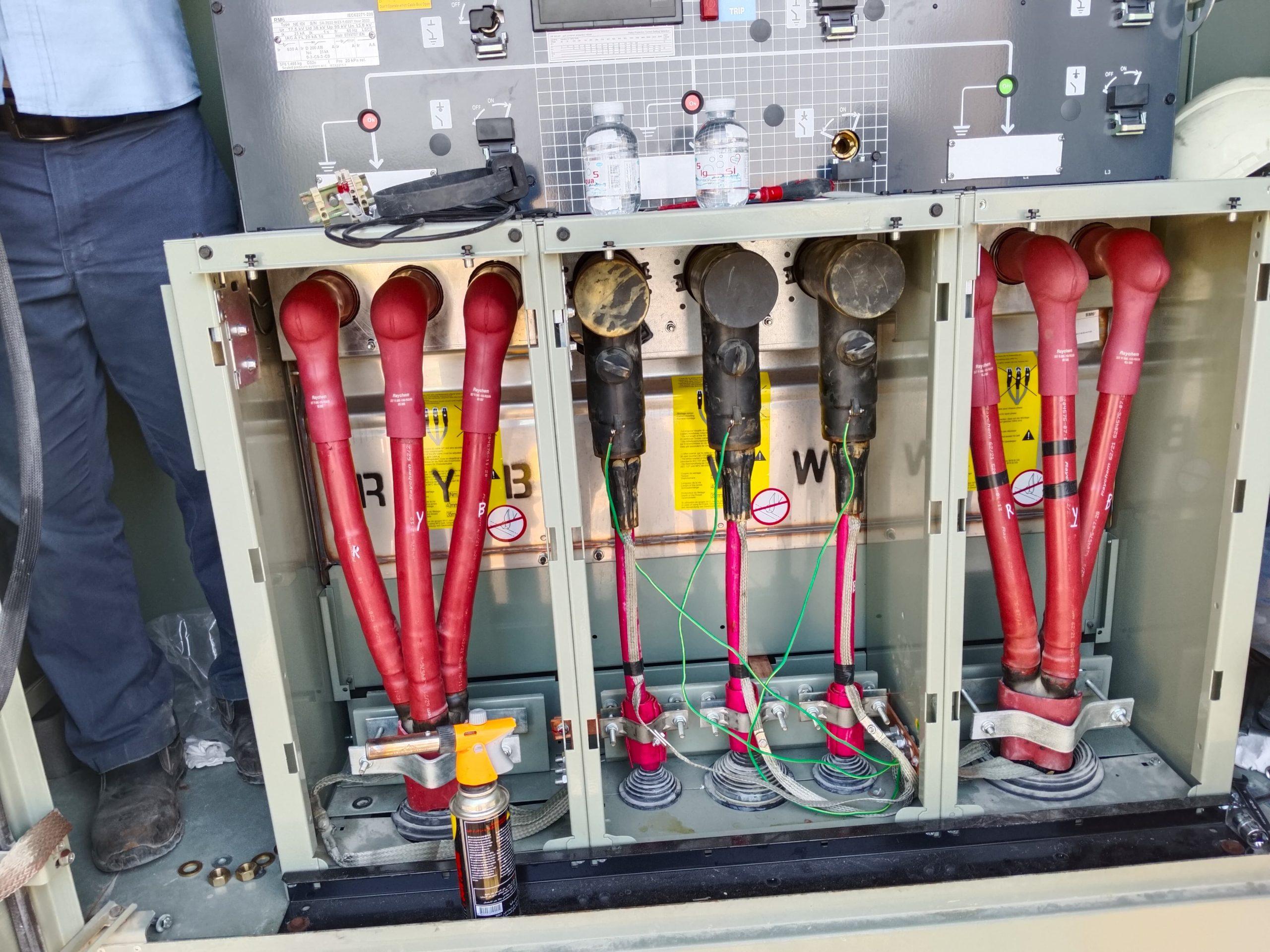
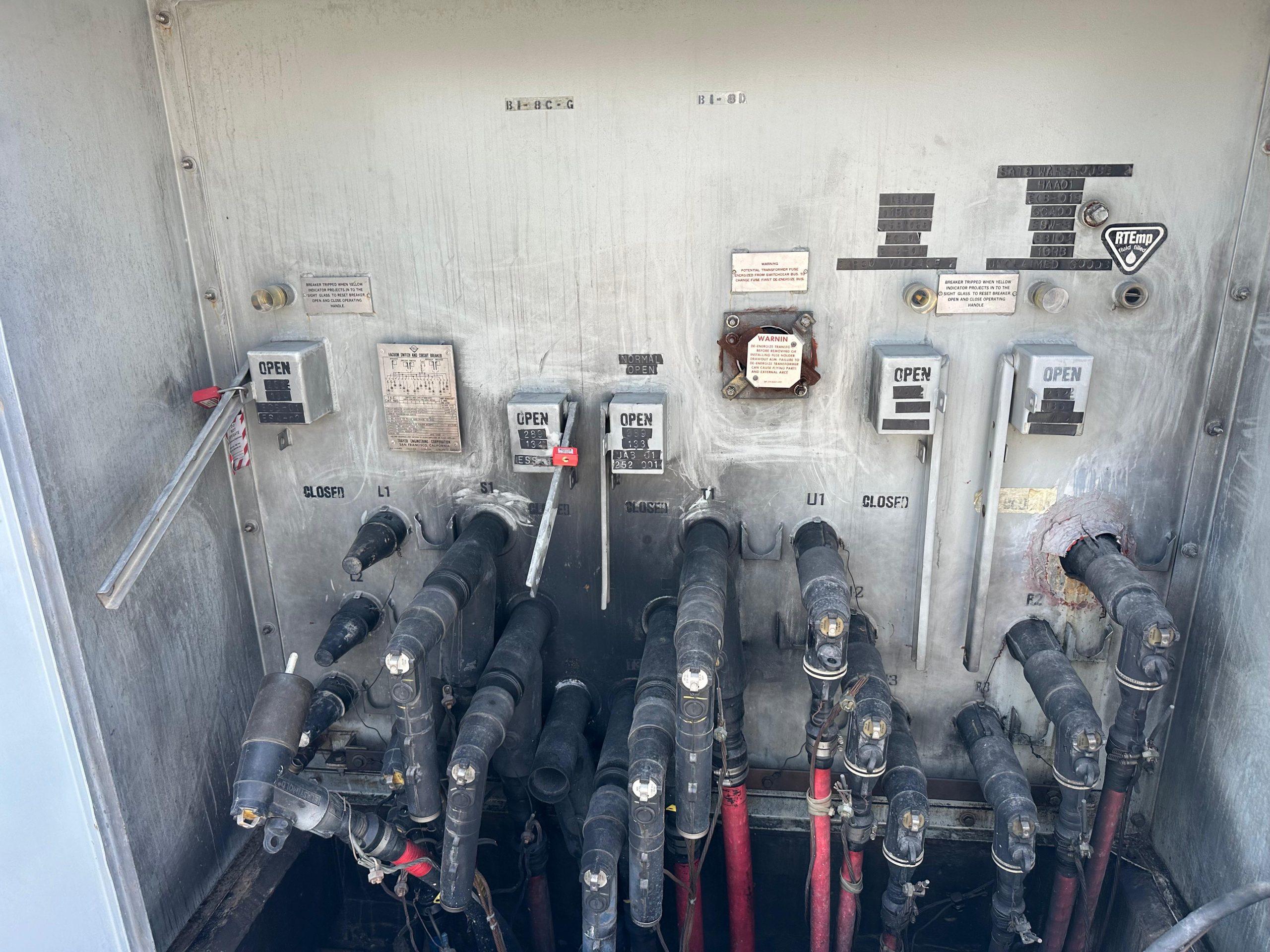
Once breaker trucks are rolled out onto transport dollies, attention moves to the fixed stationary structure: main horizontal copper busbars, vertical dropper risers, spout bushings, Current Transformers (CTs), Voltage Transformers (VTs) and outgoing medium-voltage cable terminations.
Never randomly re-torque every busbar bolt on an older switchboard without checking existing witness marks and joint resistance first. Over-tightening plated high-tensile M12 or M16 bolts stretches threads past yield and crushes Belleville conical spring washers flat, destroying the elastic clamping reserve needed when busbars heat and cool under load. Instead, inspect torque-seal paint stripes for movement, run 100 A micro-ohm measurements across every busbar splice from bay to bay, and re-make only joints showing elevated resistance, thermal discolouration or disturbed hardware—using a calibrated torque wrench set to the exact bolt grade and lubrication spec.
Instrument transformers deserve equal rigour because even the smartest numerical protection relay is completely blind if its CTs saturate or its secondary star-point wiring has two accidental earths. During major turnarounds, we verify CT insulation resistance, winding resistance, turns ratio, polarity, excitation knee-point curve (confirming metering cores weren’t accidentally swapped with 5P20 protection cores) and secondary loop burden—making dead sure every CT secondary terminal block is solidly shorted and un-shorted cleanly once testing finishes, since an open-circuited live CT generates lethal kilovolt spikes.
On draw-out VTs, check primary HRC fuse clips, verify ratio and inspect cast resin for ferroresonance crazing. Inside motor and feeder panels, disconnect ZnO surge arrester earth tails during outages to verify insulation resistance and leakage current, check fused-contactor striker pins so a single blown fuse trips all three poles, and confirm roof-mounted arc-flash relief flaps are completely unobstructed.
Five expensive switchgear maintenance mistakes our engineers still uncover on brownfield boards
Well-intentioned maintenance crews can actually lower switchgear reliability if household habits creep into high-voltage work. Across emergency call-outs and post-trip investigations in the Eastern Province and Western Region, five preventable mistakes show up again and again:
- Spraying aerosol penetrating oil (such as WD-40) onto sluggish latches: Carrier solvents flash off quickly in warm substations, leaving a sticky film that traps silica dust and seizes trip rollers months later. Always flush old grease out completely and apply only OEM-approved synthetic grease sparingly.
- Meggering SF6 compartments under low gas pressure or vacuum: Never apply high-voltage test potentials across GIS or SF6 breakers below rated density—reduced gas pressure causes internal flashover at a fraction of normal voltage.
- Skipping capacitive discharge time on long XLPE cables: After a 5 kV DC Megger test, XLPE cables retain dangerous absorption charge; bleed feeders through test-set discharge resistors and hold solid earths for several minutes.
- Forcing jammed racking lead-screws: Using an extension pipe bends interlock cams and misaligns tulip clusters onto stationary spouts—triggering immediate contact overheating under load.
- Ignoring broken-delta VT damping resistors: On ungrounded or impedance-grounded buses, an open damping resistor lets switching transients excite ferroresonance that cooks cast-resin VTs.
Testing numerical protection relays and the 110 V DC battery supply
Modern feeder, transformer-incomer and motor-protection IEDs (ABB Relion REF615/630, Siemens SIPROTEC 7SJ/7UT, Schneider Sepam/Easergy, Schweitzer SEL-751, GE Multilin) rarely drift in digital math the way old electromechanical induction discs did. Yet secondary injection testing still catches critical field defects on nearly every plant shutdown we execute: analog input scaling mismatches after a firmware update, oxidized binary output relay contacts that weld or fail to close onto trip coils, unverified arc-flash optical sensor loops, and broken GOOSE / interlocking trip logic between incomers and bus-section couplers.
Using calibrated three-phase secondary injection sets (Omicron / Megger / Sverker), our protection engineers validate pickup thresholds and operating times across phase overcurrent (50/51), earth fault (50N/51N), directional earth fault (67N), under/over-voltage (27/59), motor thermal overload (49) and busbar/transformer differential (87) elements against the plant’s approved coordination study.
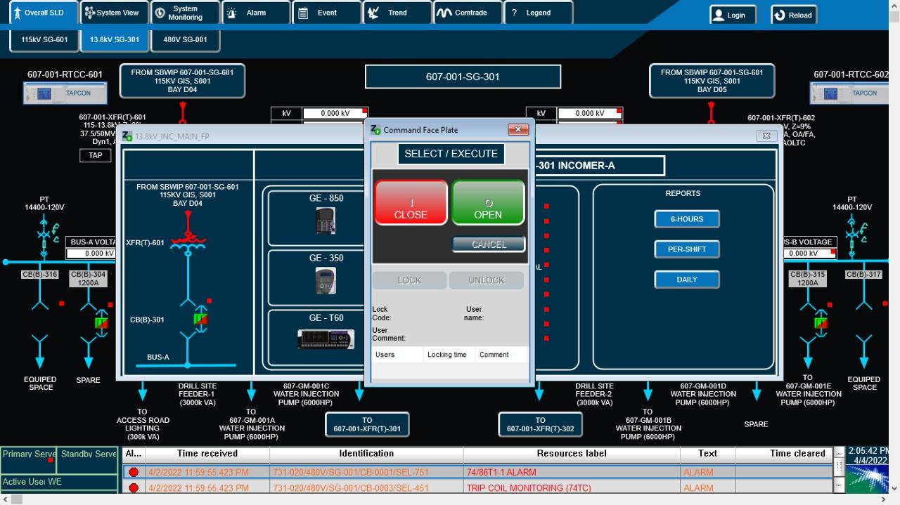
Crucially, simulation stops short if you only watch an LED light up on the relay faceplate. Every protection maintenance scope must finish with a live functional trip-matrix test: injecting fault current into the CT test block and letting the relay physically trip the main circuit breaker, lock out the 86 master lockout relay, initiate breaker-failure (50BF) inter-tripping to adjacent bays, and stamp the exact sequence-of-events (SOE) alarm onto the control room substation SCADA HMI.
Don’t overlook the substation DC battery charger and battery bank next door. A multi-million-riyal 33 kV switchboard cannot trip if two high-impedance cells pull the 110 V DC bus below 65 V under coil load; cell impedance checks, inter-cell micro-ohm readings and charger ripple tests belong on every annual checklist.
Structuring a 6-month, annual and 3-year switchgear maintenance calendar
Over-maintaining switchgear by racking trucks in and out needlessly every quarter wears mechanical shutters faster than leaving them alone; under-maintaining panels for seven years invites catastrophic flashovers or seized mechanisms like those that force emergency 72-hour switchgear replacement turnarounds. For industrial plants, utilities and commercial infrastructure in Saudi Arabia, a balanced three-tier schedule aligns non-intrusive online checks with planned process shutdowns.
Where switchgear feeds high-value upstream assets such as 220 MVA refinery GSU transformers or 150 MVA petrochemical power transformers, combining this structured calendar with permanent online thermal and PD sensors safely stretches invasive shutdown intervals while raising asset availability.
| Maintenance Tier | Recommended Interval in KSA | Outage Needed? | Field Scope & Deliverables |
|---|---|---|---|
| Tier 1 · Condition & Environmental Walkdown | Every 6 Months (Pre-Summer & Post-Summer) | No — Live | IR thermography via crystal ports, handheld TEV/ultrasonic check, room HVAC/humidity audit, panel heater ammeter check, SF6 pressure gauge log & DC charger ripple check. |
| Tier 2 · Functional Exercise & Relay Health | Every 12–18 Months (Minor Feeder Window) | Feeder-level only | Controlled breaker open/close exercise, trip-circuit supervision & 86 lockout check, DC battery cell impedance test, relay self-diagnostic/event log download & filter cleaning. |
| Tier 3 · Full Shutdown Diagnostic Overhaul | Every 3–5 Years (Plant Turnaround) | Full Bus Section Outage | HEPA/IPA compartment clean, 100/200 A contact resistance, breaker timing/travel/coil curves, vacuum/SF6 integrity, busbar joint micro-ohm audit, CT/VT verification & full secondary-injection trip matrix. |
| Post-Fault Mandatory Inspection | After Clearing Major Short-Circuit Duty | Targeted Bay Outage | Immediate cumulative I²t contact-erosion check, vacuum bottle integrity test, arc-chute inspection and tulip finger examination before returning breaker to auto-reclose/service. |
Whether you manage a single 13.8 kV ring main loop or twenty substation buildings across an Eastern Province industrial complex, clean baseline test sheets are worth their weight in gold when troubleshooting future anomalies. Explore more substation reliability guides on our technical articles hub, review our power transformer leak prevention guide, or request a switchgear maintenance proposal from Petrozone’s Al-Khobar testing and commissioning division.
More from our engineers & field teams
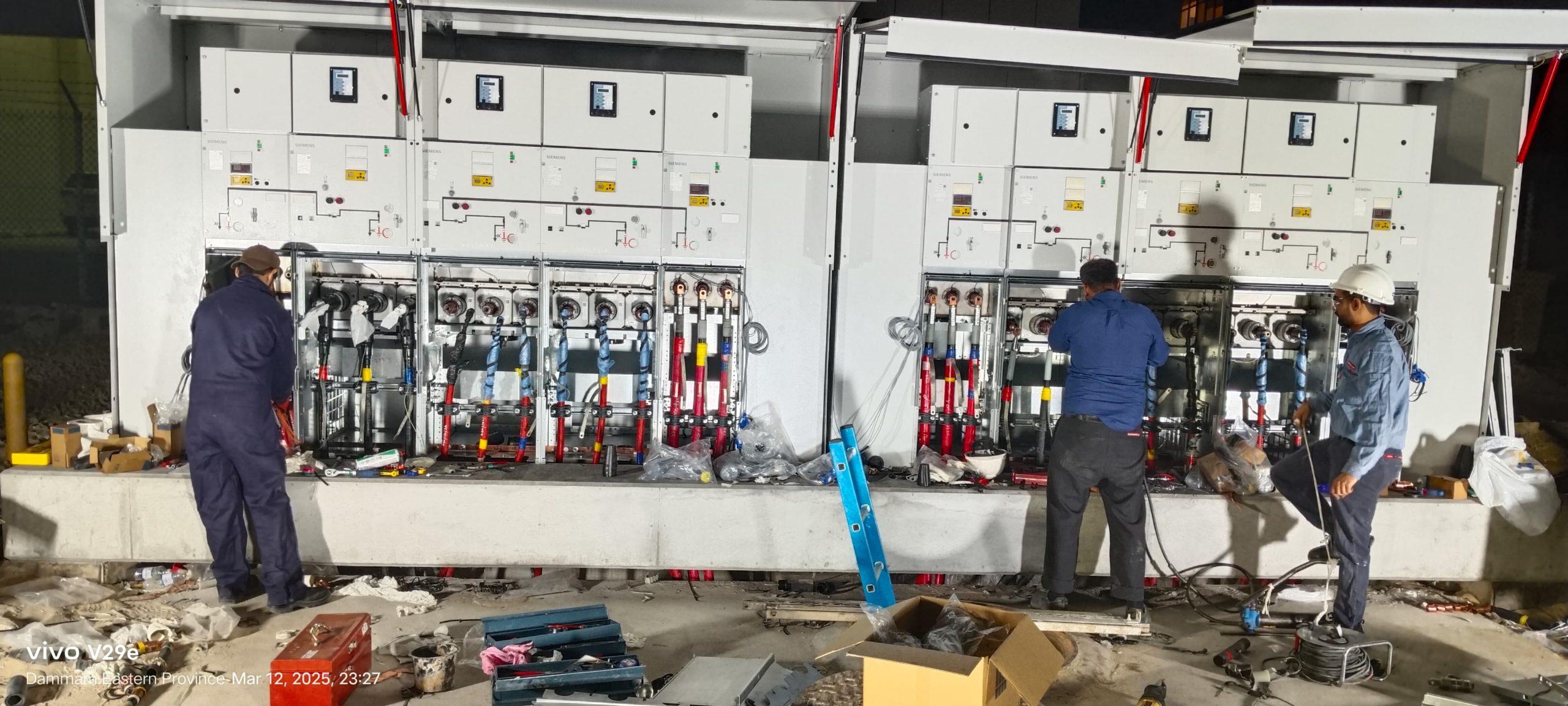
A 72-hour turnaround for RMU replacement & MV cable termination
Day-and-night replacement of an aging ring main unit, medium-voltage cable termination and commissioning completed within a strict 72-hour window in Saudi Arabia.
Read article →
Critical 220 MVA GSU transformer maintenance for leading Saudi refinery
High-precision turnaround maintenance, insulating oil treatment and diagnostic verification executed on schedule at a major refinery in Saudi Arabia.
Read article →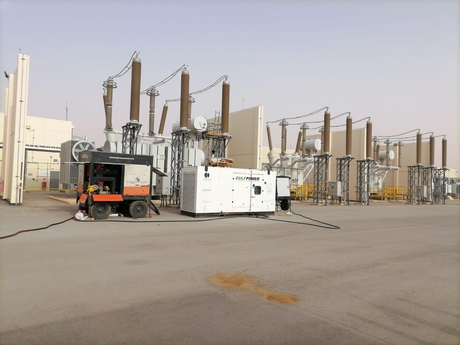
Repairing oil leaks on 150 MVA power transformers at a Saudi petrochemical plant
Full-scope leak remediation across radiator flanges, pressure relief devices and valve connections to restore reliability on critical high-voltage units.
Read article →Planning a project? Talk to the right division.
Send us the scope, location and timeline. We will reply with the right team and a quote.